News
August 2025:
What’s new in EZ-CAM 2026 (V33) - The Video
Discover the latest innovations in EZ-CAM 2026!
This video walks you through the most impactful enhancements in the new version of EZ-CAM CAD/CAM software.
Whether you're a machinist, programmer, or workshop owner, EZ-CAM 2026 delivers tangible benefits that make your CNC workflow faster, easier, and more reliable.
● Fully reworked interface with modern usability
● Curve-free machining enhancements
● Advanced 3D wizard with solid model recognition
● Improved tool library with ISO 13399 integration
● New post-processor updates
● Seamless data backup and restore between versions
Each new release is shaped by feedback from global EZ-CAM users and aims to boost productivity, reduce programming errors, and simplify daily machining tasks.
Ideal for:
● CNC programmers
● Machine shop owners
● CAM educators and trainers
● Existing EZ-CAM users upgrading to v2026
June 2025:
Ez-Cam 2026 - Is here.
What’s new in EZCAM Version 2026
1. Industry-Leading 3D Toolpaths
The 2026 edition introduces an entirely new generation of high-performance toolpaths:
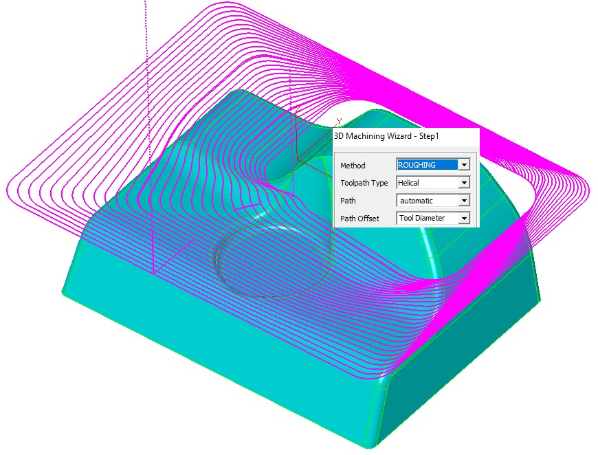
3D Roughing
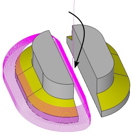
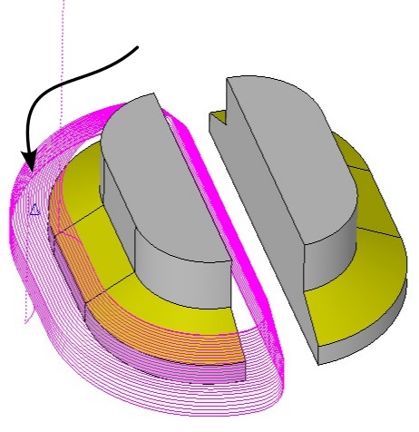
● Auto side lead-in/out from stock boundary enables the tool to automatically lead in and out from the edge of the stock material, ensuring safe entry and exit without engaging the part.
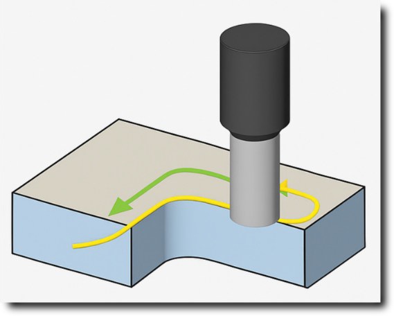
● If helical plunging is not feasible due to a narrow area, the system automatically switches to Zig-zag within the limits and continues safely without showing an error.
● Minimize Jumps option replaces Z-rapid retracts with optimized safe-Z lifts, eliminating unnecessary retracts to high clearance planes for smoother and more efficient toolpaths.
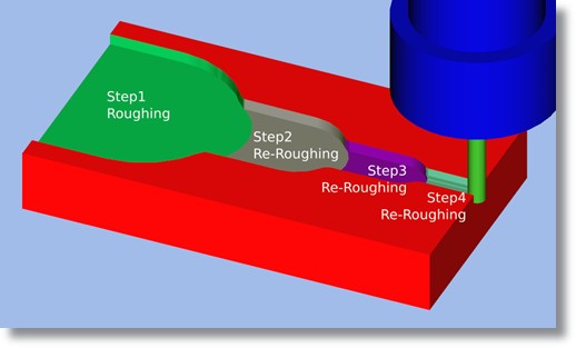
3D Re-Roughing
● Independent control over re-roughing parameters allows a separate set of plunge settings, machining allowances, finish tolerances, and boundary definitions to be applied, enabling toolpaths to be precisely tailored for both roughing and re-roughing.
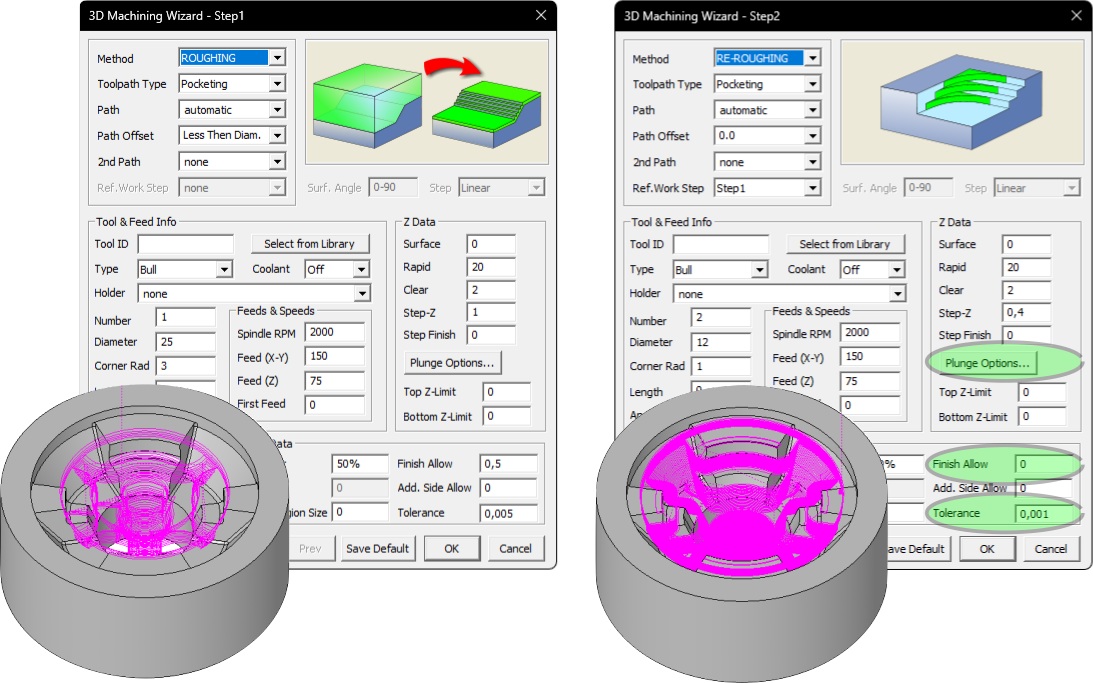
● Accurate rest material computation for all tool types ensures precise detection of uncut material regardless of tool type, improving efficiency and accuracy in re-roughing and finishing sequences.
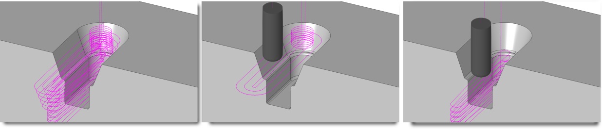
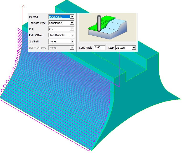
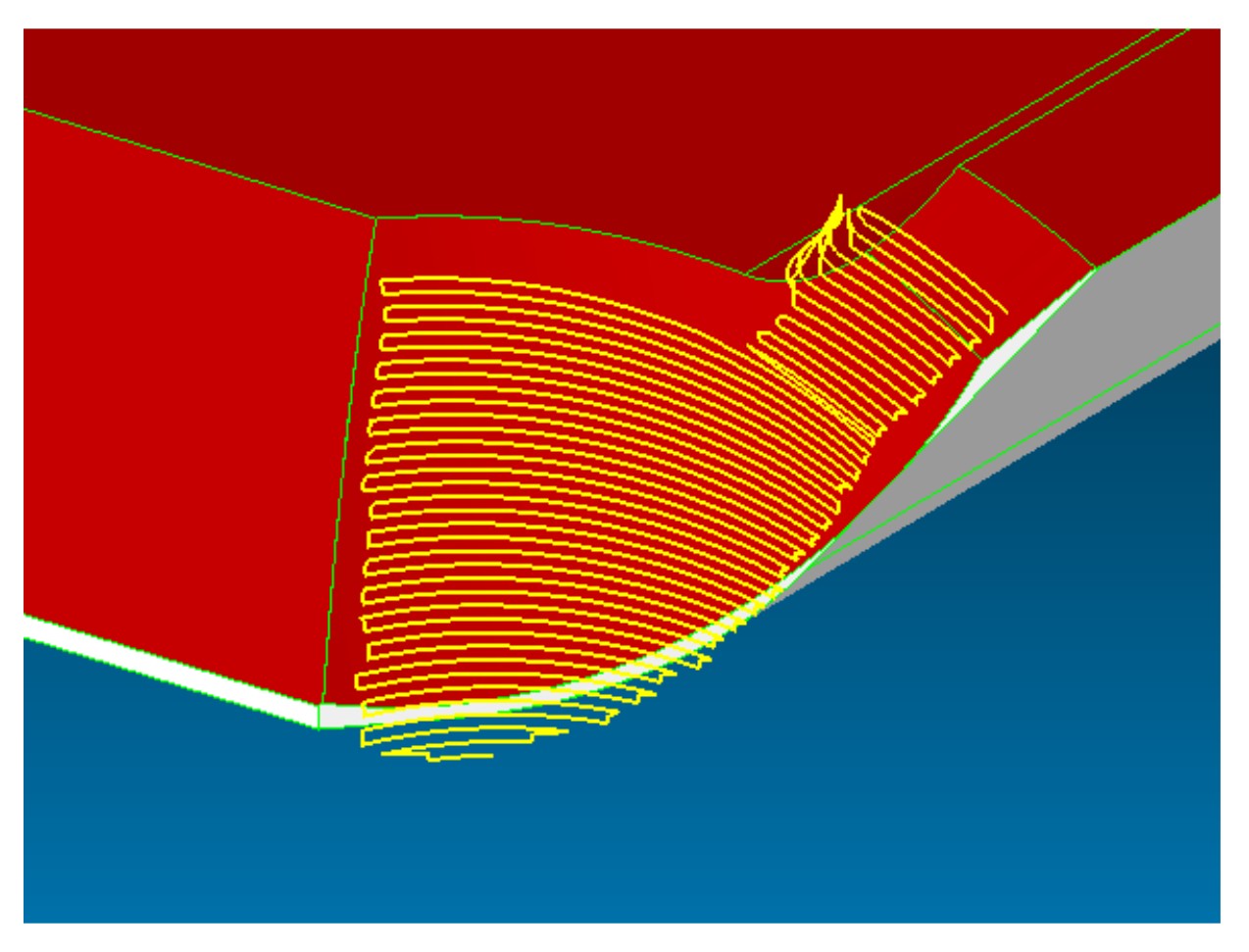
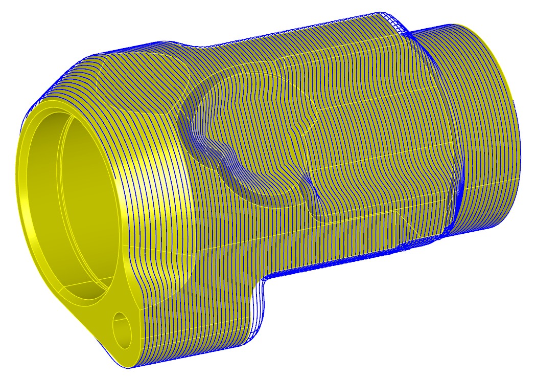
New 3D Finishing Strategies
● Parallel, Radial, Morphcut, Curve Projection
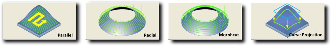
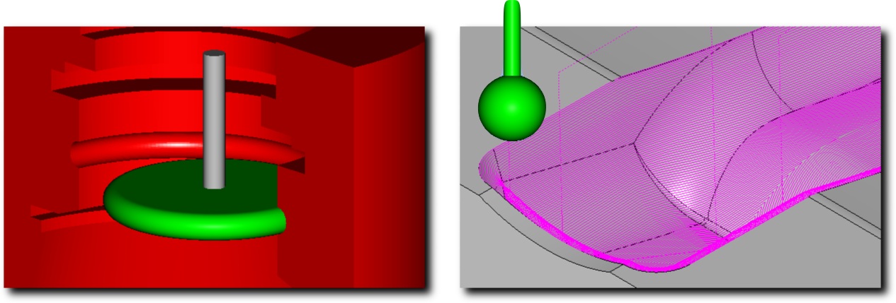
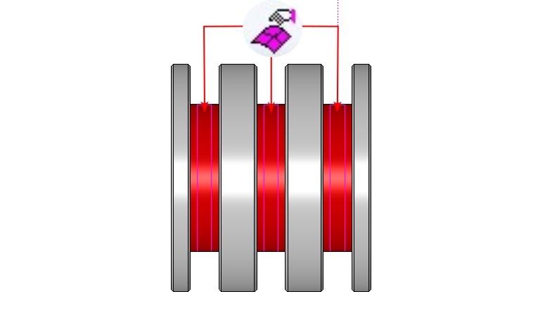
● Supports undercut tools such as T-slot and lollipop cutters.
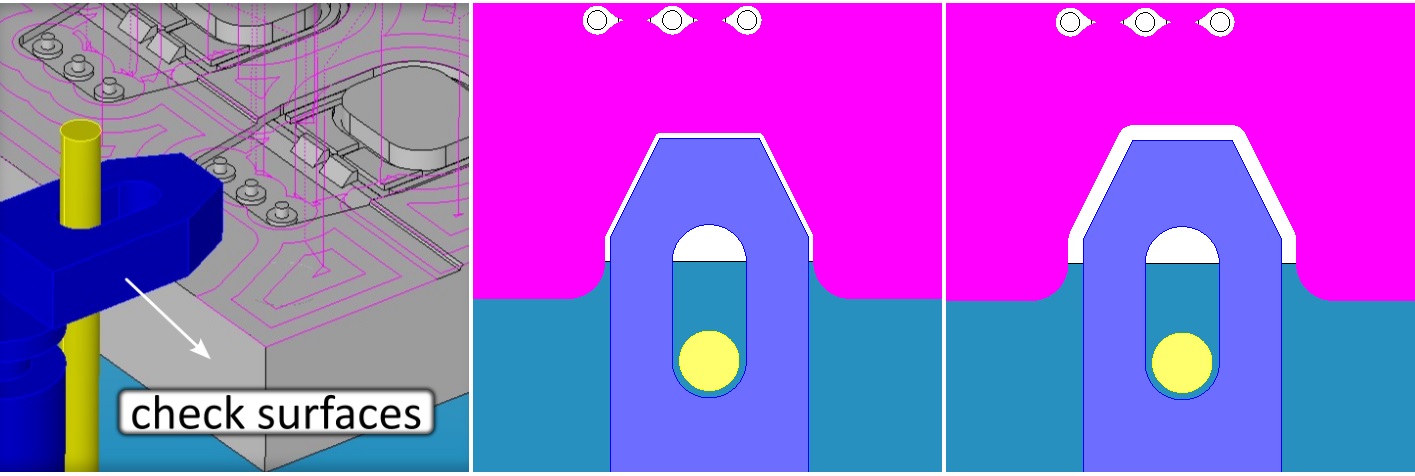
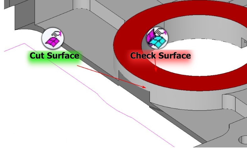
● Supports selection of Check Surfaces and specification of minimum and maximum Surface Angle parameters to restrict toolpath generation to the desired regions.
● Smooth automatic ramp in/out
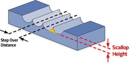
● Variable Step mode for consistent scallop height
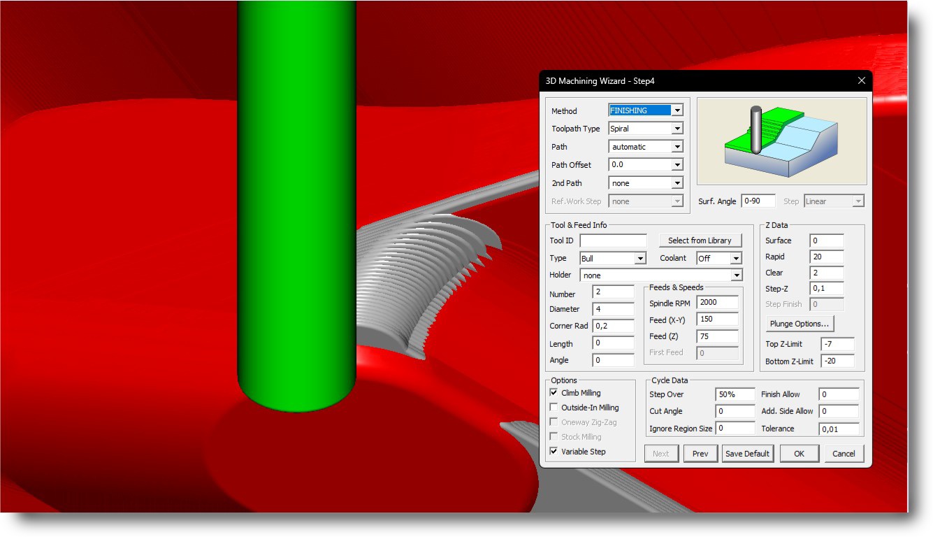
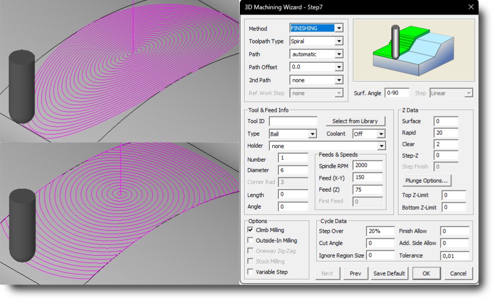
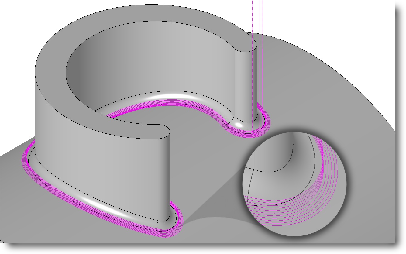
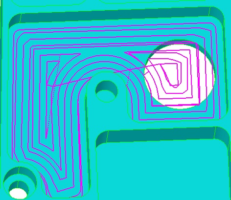
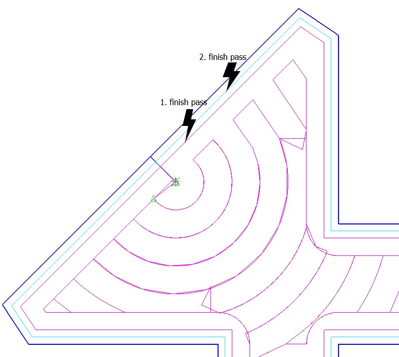
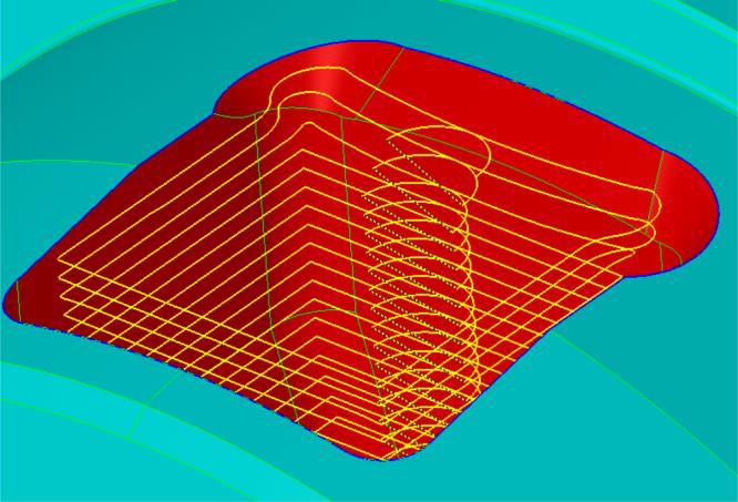
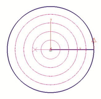
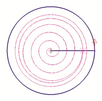
Spiral Finish
● Automatically transitions to elliptical spirals for wide areas, maintaining tool efficiency and surface quality
● Users can define both the cutting direction and the starting point of the operation for better control.
● Allows the addition of dedicated finish passes within spiral operations for enhanced precision
● Variable Step maintains scallop tolerance while optimizing X-Y step length
Pencil Milling Enhancements
● Adds support for multiple pencilcut passes, ideal for detailed edge cleanup and improved surface quality
● Also supports constant-Z passes by specifying the Z step parameter
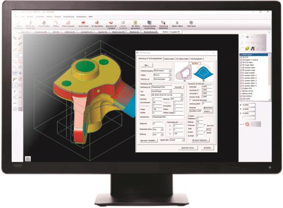
2. Next-Gen Wizard Interface
Redesigned UI with modern visuals and always-visible data panels. Help graphics enhance understanding during toolpath setup.
● Faster Programming and Simulation In previous versions, users had to close the workstep dialog to calculate toolpaths, select surfaces, or initiate simulation. Now, all these steps can be performed directly while the window remains open. You can even exit simulation mode by simply double-clicking an empty space on the screen—no need to use the Redraw command.
● Right-Side Command Panel 2D Wizards now appear above the workstep list for improved workflow access. From here, you can initiate a new workstep, enter tool parameters, and select geometry—all without ever closing the active window.
● Seamless Workstep Navigation You can now switch between ez-cam commands and workstep editing with a single click. Toolpath recalculation is available while the window remains open, making it easy to iterate quickly.
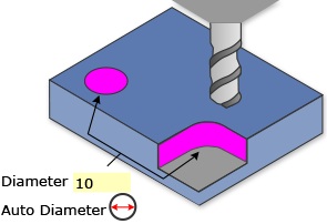
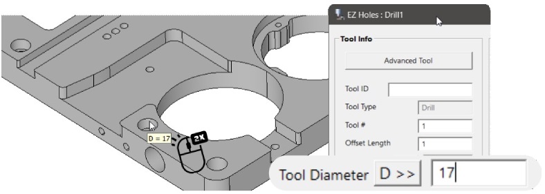
● Automatic Tool Diameter A new button next to the input box enables the tool diameter to be set automatically based on the current selection. For drilling operations, it matches the diameter of the selected holes. For contouring and pocketing operations, it matches the minimum corner fillet radius of the selected faces.
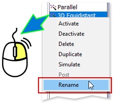
● In-Place Renaming A new right-click feature allows for easy renaming of worksteps directly in the list—just right-click and rename.
3. Curveless System Improvements
Curveless now supports: pocketing, contouring, chamfering, wrapping, 4th-axis, drilling, threading.
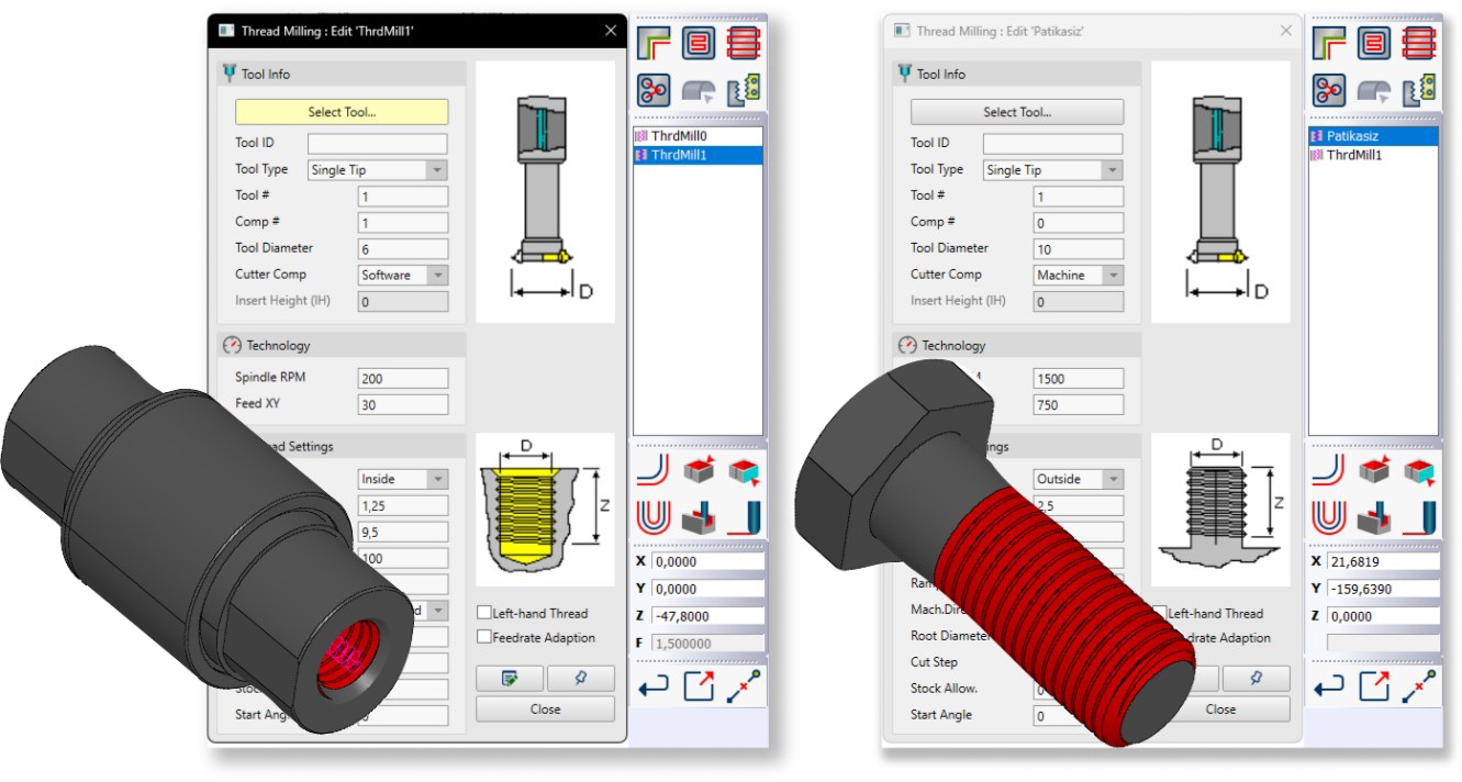
● Threadmilling face-based SmartClick support for internal and external threads
● Wrapping with Open-End Pockets supported in EZ-MILL and EZ-TURN
● Pocketing/Contouring with Bosses Combine Regions supports embedded features
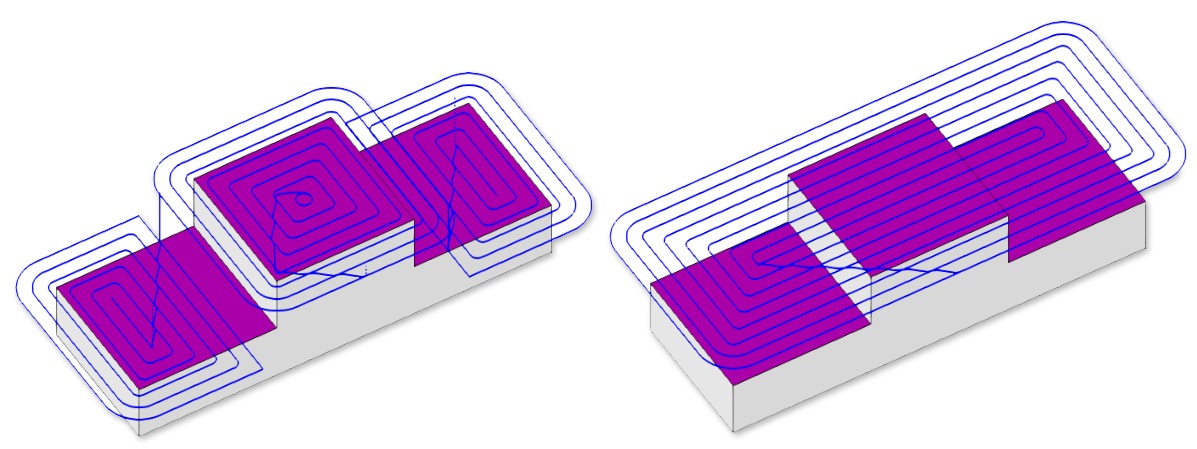
● Check Surface Expansion supported in more pocketing/contouring cases
● Open-Edge Contouring with check surfaces and auto region detection
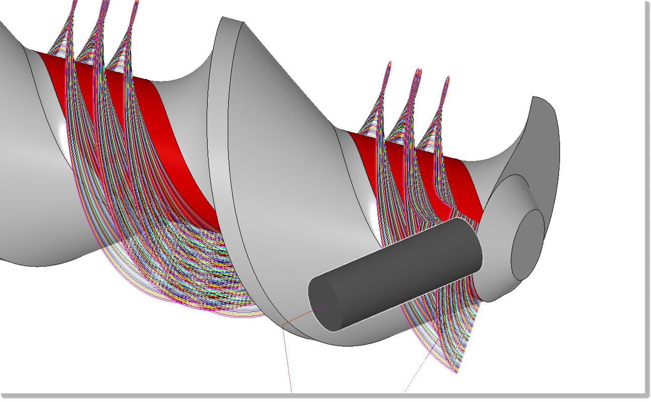
● 4th Axis Surface Finishing via contour with 3D projection (EZ-TURN)
● SmartClick Enhancements
o Selects flat faces at same Z height; ignores blind hole ends
o Supports wrapping via face selection at same diameter
o Draft/taper angles automatically populated
o Automatically set Z-surf and Z-depth
o Avoids faces with negative surface normal
o Allows curveless indexing without UCS using first selected surface
4. Workflow, Automation & Integration Enhancements
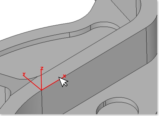
● Enhanced “World on Surface” Command
o
Dynamic X-Axis Alignment: When the cursor is moved near a linear edge of the selected face, the X-axis of the UCS
automatically aligns with that edge. This intuitive preview helps the user understand how the UCS will be oriented
before placing it.
o
Endpoint-Based Direction Control: The system intelligently chooses the X+ direction based on the proximity of the
cursor to the endpoints of the selected edge, allowing more precise orientation without requiring manual axis flipping.
● EZ-WEB Tools
o Backup/restore from “default account” tied to license key
o New option to upload user-selected files
o Restore log opens in preferred text editor
o Backup/restore access directly from Starting Window
o Better exception handling prevents crash scenarios during upload / download
● UI & Automation
o Double-clicking empty space now triggers Redraw
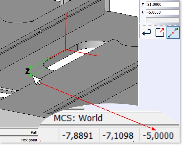
o
True 3D Screen Point Snapping: When hovering over a surface, the “Screen Point” snapping mode now locks to the
actual 3D coordinates of the model allowing reliable distance measurements.
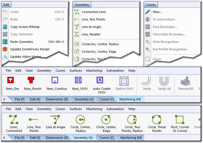
o Geometry Copy/Paste works across layers and EZ-CAM modules
o Spreadsheet command can sync Tool Data across all worksteps using same tool number
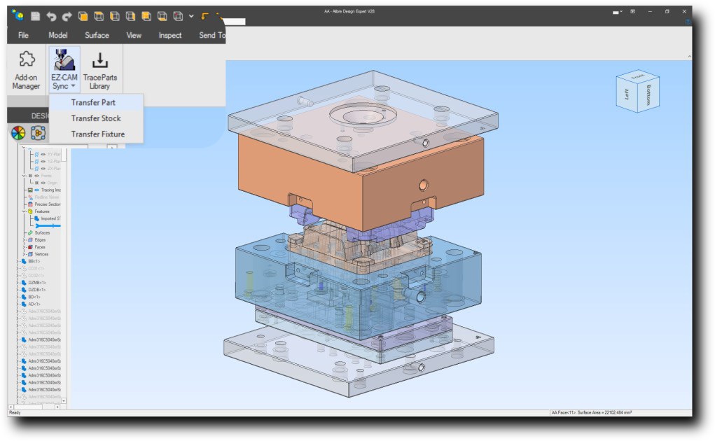
● Alibre Enhancements
o “Transfer Fixture” and “Transfer Stock” supported
o When working with assemblies in Alibre, using the “Edit Here” or “Edit in Separate Window” command on a specific
component ensures that the part retains its precise placement during the transfer into EZ-CAM
o Feature data from design tree now transferred (e.g., fillet radius for 3D geometry)
● SolidWorks Plug-in
o Improved model transfer reliability
o Better handling of special characters and face properties
5. EZ-EDM: Redesigned Icons for All Commands
All command icons have been redesigned in a larger 32 x 32 size to improve visibility and usability. The new icons ensure a visually cohesive interface, making commands easier to recognize and access.
December 2024:
Ez-Cam 2025 - Is here.
What’s new in EZCAM Version 2025
Redesigned Icons for All Commands
All command icons have been redesigned in a larger 32 x 32 size to improve visibility and usability.
The new icons ensure a visually cohesive interface, making commands easier to recognize and access.
EZ-MILL – Curveless Programming Enhancements
Machine pockets of various types – open-ended, closed, with or without undercuts – all within a single curveless Pocketing workstep. This feature eliminates the need for defining multiple worksteps, one for each pocket, significantly improving workflow efficiency.
EZ-MILL
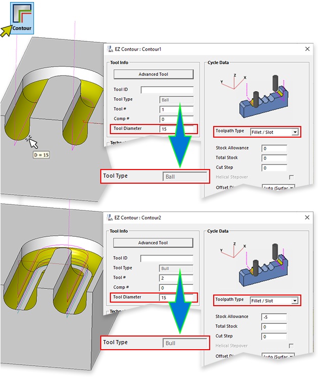
We have introduced the new “Fillet / Slot” toolpath type to the Contour wizard. Both flat and half-round slots can now be machined with the quickest possible method. If the tool size does not match the "constant width" of the slot and EZ-CAM adjusts the curve allowance automatically to achieve center-line toolpath. The new feature also allows processing interior and exterior fillets directly without setting up additional parameters.
EZ-MILL
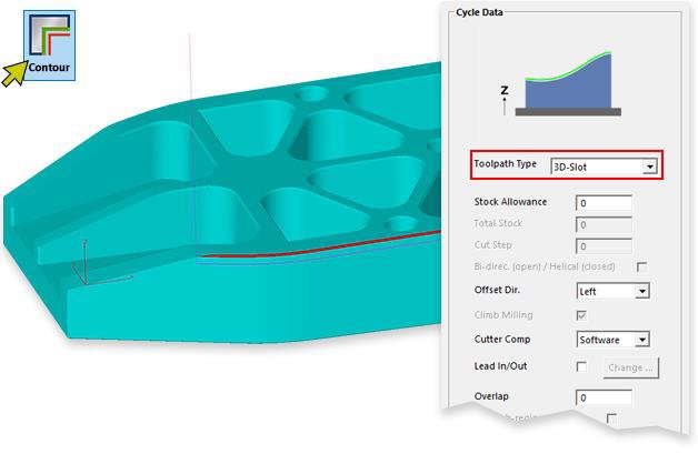
“3d Curve” toolpath type of the Contour wizard has been enhanced to handle cut surfaces with 3D bottom edges.
Using the new feature 3D chamfering can be accomplished with unmatched speed.
EZ-MILL
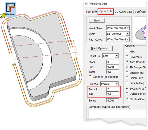
Contouring worksteps with Toolpath Type selected as “Multiple Passes” supports Tab Width and Tabs # settings eliminating the need to create multiple worksteps, one for each cutting depth.
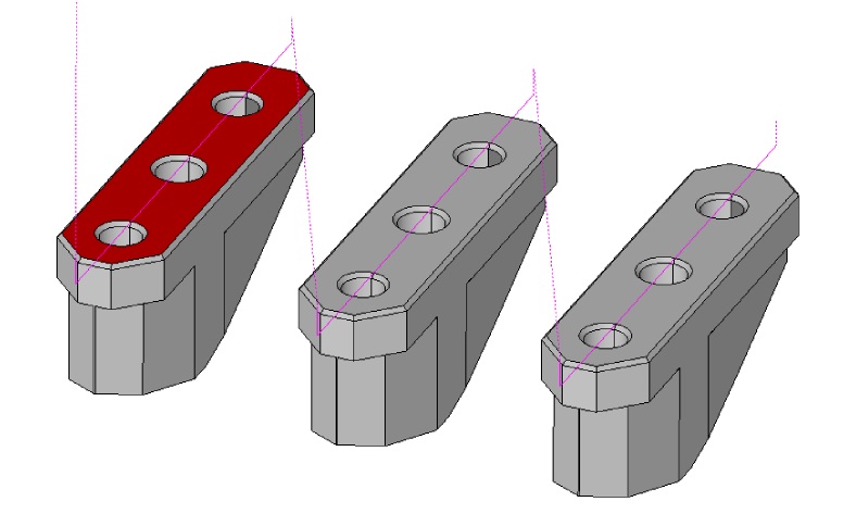
EZ-MILL
Contouring with “Multiple Passes” toolpath type has been extended to remove the material between the tapered wall and the stock. Setting the Total Stock parameter to zero allows the system to calculate the total depth for each Z-level dynamically, ensuring optimized material removal.
EZ-MILL
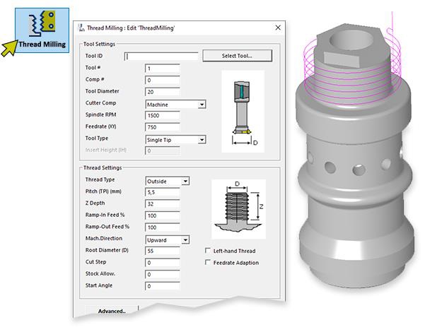
Curveless thread milling is now available on any selected User Coordinate System (UCS), offering users more control over thread milling operations, especially for non-standard orientations.
EZ-MILL
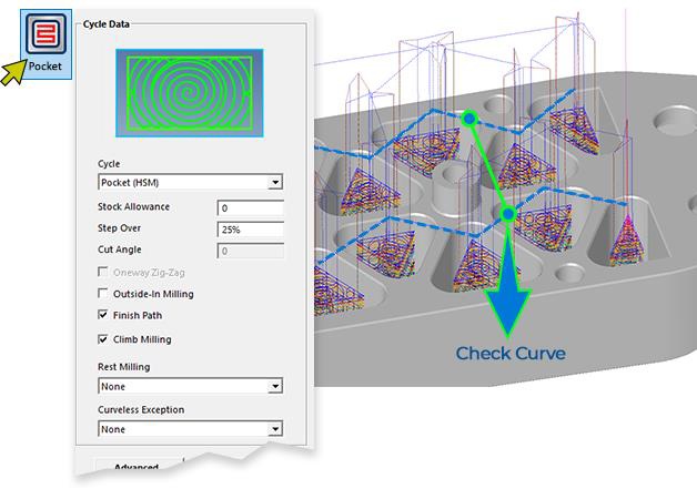
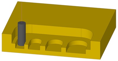
Users can now define multiple plunge points using a check curve consisting of rapid moves only. The system automatically selects the appropriate plunge location for each cavity, improving machining efficiency for complex parts.
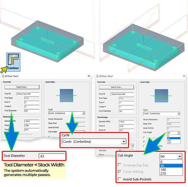
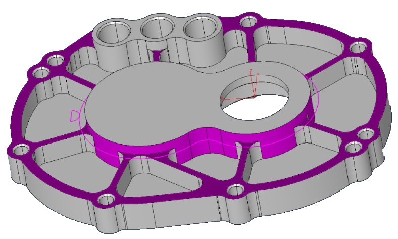
EZ-MILL
Centerline contouring method has been greatly enhanced. Z-Surf data is automatically retrieved from the selected stock surface. Cut angle can be set as 90, 180, 270. If the tool size is detected to be smaller than the stock width, the system automatically generates multiple passes to ensure complete material removal.
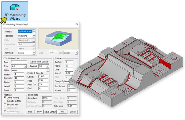
EZ-MILL – 3D Wizard Re-Roughing Improvements
● Toolpath calculations in the 3D Wizard Re-Roughing feature have been optimized, resulting in a 30% performance boost.
● Toolpath verification and posting can now be interrupted using the ESC key, providing greater control over long operations.
● If no parameters have been modified since the last toolpath calculation, the Verify and Post commands produce results instantly, saving time during repeated operations.
EZ-MILL – HSM Trochoidal Pocketing Enhancement
● HSM has already included lead-out moves to avoid rapid up along the surface; this module has now been extended to automatically add lead-in moves at all plunge locations to avoid cutting down with the full size of the cutter.
● When HSM strategy divides the pocket into separate regions due to large cutter size, each region is handled separately allowing entrance at open boundary if exists.
● Overlap setting defines additional plunge distance away from the open edge of the model.
EZ-MILL – Stock Handling Capabilities
● New Command for Alibre Plug-in: Easily transfer the current model as stock data with the name “stocksrf.”
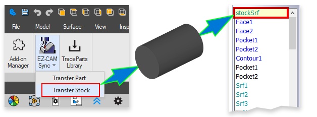
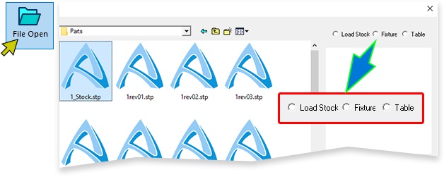
● Expanded Import Options: IGES and STEP imports now offer the ability to load CAD data as stock, fixture, or table model, a feature previously available only for STL files.
EZ-TURN
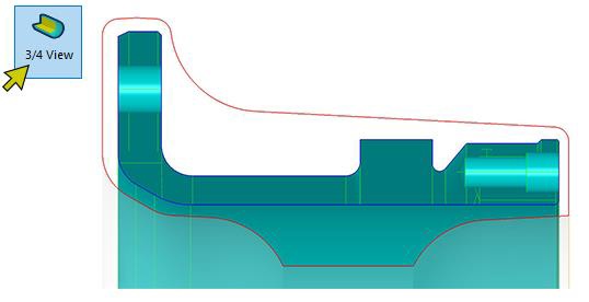
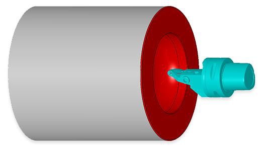
● Automatic Stock Orientation in EZ-TURN: The stock is now automatically oriented with its rotational axis aligned to the Z-direction, matching the part model.
● 3/4 View Command in EZ-TURN: The spun profile of the stock model is now displayed in red, enabling easy visualization and data creation.
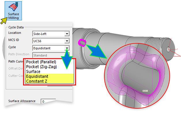
EZ-TURN – Curveless Programming Enhancements
The new version introduces additional 3D finish strategies to the EZ-TURN environment. The Equidistant and Constant-Z methods enhance surface milling capabilities within mill-turn cycles. Additionally, the machining boundary is now computed automatically based on the selected cut and check surfaces, simplifying setup and improving precision.
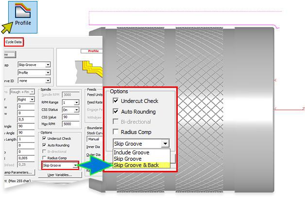
EZ-TURN
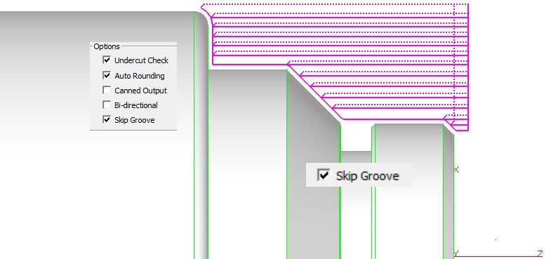
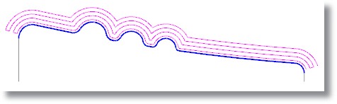
Since the first introduction of the skip groove feature, if the part has a "hump" in the middle of the part such as shown in the below figure, regions at the left side of this hump have been dismissed. Now the updated feature introduces the new option “Skip Groove & Back” makes this behavior optional.
EZ-TURN
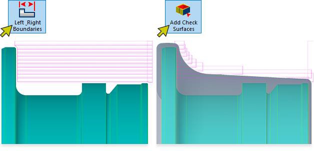
Users needing to define the outside turning boundary, such as when working with cast parts, can now select the stock model as a check surface. This eliminates the need to manually create and select a custom boundary path curve, streamlining the setup process and improving efficiency.
EZ-TURN
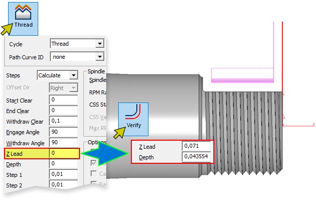
The new version extends threading support in our curveless system. When Z-Lead is left as 0, the system automatically computes Z-Lead and Depth parameters from the model data within set boundary limits. Mill-turn parts where the threading operation is partially overtaken by the milling feature are also supported.
EZ-TURN
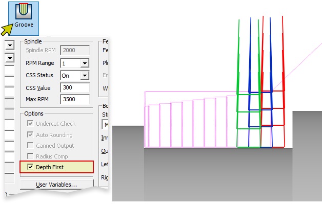
The Groove cycle in EZ-TURN has been enhanced with the addition of a new Depth First option. When enabled, this option ensures that each pass is executed in a pecking style, progressing to the full depth before performing the sideways stepover. This approach improves chip management by allowing for effective chip break, enhancing cutting performance and tool longevity.
EZ-TURN
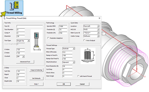
Curveless Thread Milling is now available in EZ-TURN. A new command button is added to the Mill/Turn tab to setup its parameters followed by the selection of the faces of the holes to be threaded.
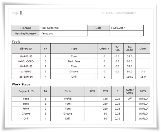
EZ-TURN – Enhanced Tool Holder Creation
Turning tool holders can now be generated directly using the Silhouette command with imported or transferred 3D model data. Previously, users had to manually define a 2D profile for the holder, making the process faster and more streamlined in this version.
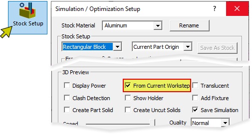
New Simulation Mode
A new checkbox, “Start from Current Workstep,” has been added to the stock parameters window. When selected, the simulation button or command runs in this mode, allowing users to skip ahead and focus only on relevant parts of the toolpath.
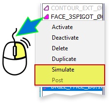
Extended Popup Commands for Workstep ListBox
● Quick Post Output Generation A new Post command has been added to the right-click popup menu in the workstep listbox. Users can now create and review post outputs for all selected worksteps quickly from the list.
● Enhanced Simulation Control When any workstep is right clicked, selecting Simulation from the popup processes the toolpaths of all previous worksteps in the background, enabling a quick simulation to start from the chosen workstep.
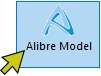
Alibre Model Connectivity
Improved Integration: Resolved issues with model connectivity for Alibre files. EZ-CAM now maintains connections after saving and reopening, ensuring smoother workflows between EZ-CAM and Alibre.
December 2023:
Ez-Cam 2024 - Is here.
What’s new in EZCAM Version 2024
MILL-Pro – Clearance Allowance for Check Surfaces
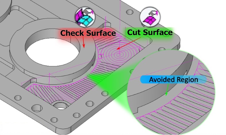
The roughing and finishing methods in 3D-Wizard enable users to define boundaries by selecting check surfaces as avoid regions. In this scenario, the toolpath is restricted to remain within the boundaries defined by the selected cut and check surfaces. In version 2024, we have introduced support for an extra clearance allowance specifically applied to check surfaces. As an illustration, this new feature allows users to avoid "pads" with a clearance allowance different from those of the cut surfaces.
MILL-Pro – Start Point for Constant-Z Finishing Method
You can now define the start point for the constant-z finishing method within 3D-Wizard. By choosing a single-point curve designated as the "Path Curve," you can pinpoint the safe location for ramp moves. If you also need to define the machining boundary using a curve, select it as the "2nd path".
MILL / MILL-Pro / MILL Express – Check Surfaces for Curveless Operations
Check Surface support has been added to curveless pocketing and contouring methods. 2D Silhouette boundaries of the selected check surfaces are used as avoid regions by the new curveless toolpath engine. This feature allows 2,5D toolpath creation for complex shapes even with undercut areas without going through cumbersome geometry / curve creation and editing process.
MILL / MILL-Pro – Curveless 4th Axis Wrapping
The Curveless system has introduced enhanced support for 4th axis wrapping, accommodating both closed and continuous pockets that encircle themselves. This feature leverages the edge geometry of chosen cut surfaces to establish the wrapping boundary. Elements positioned beyond the wrapping diameter, as defined by the Z-Surf and Z-Depth parameters, are automatically excluded. In cases where all elements fall outside the wrapping diameter, the complete edge boundary is embraced as the guide for the process.
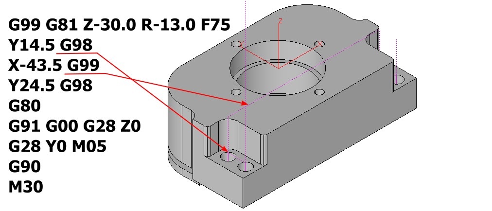
MILL / MILL-Pro / MILL Express – Curveless Drill Operations with Check Z-Clear
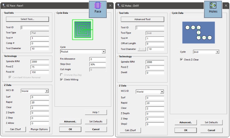
In Curveless drill operations, the system performs an automatic check to assess potential obstructions between holes. It intelligently determines where to issue G80 commands and initiates rapid traverse movements at the Z-rapid plane, ensuring a smooth and efficient drilling process. In some cases where this automatic behavior is not desired it can be turned off using the new “Check Z-Clear” setting in the Holes wizard.
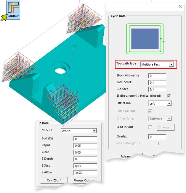
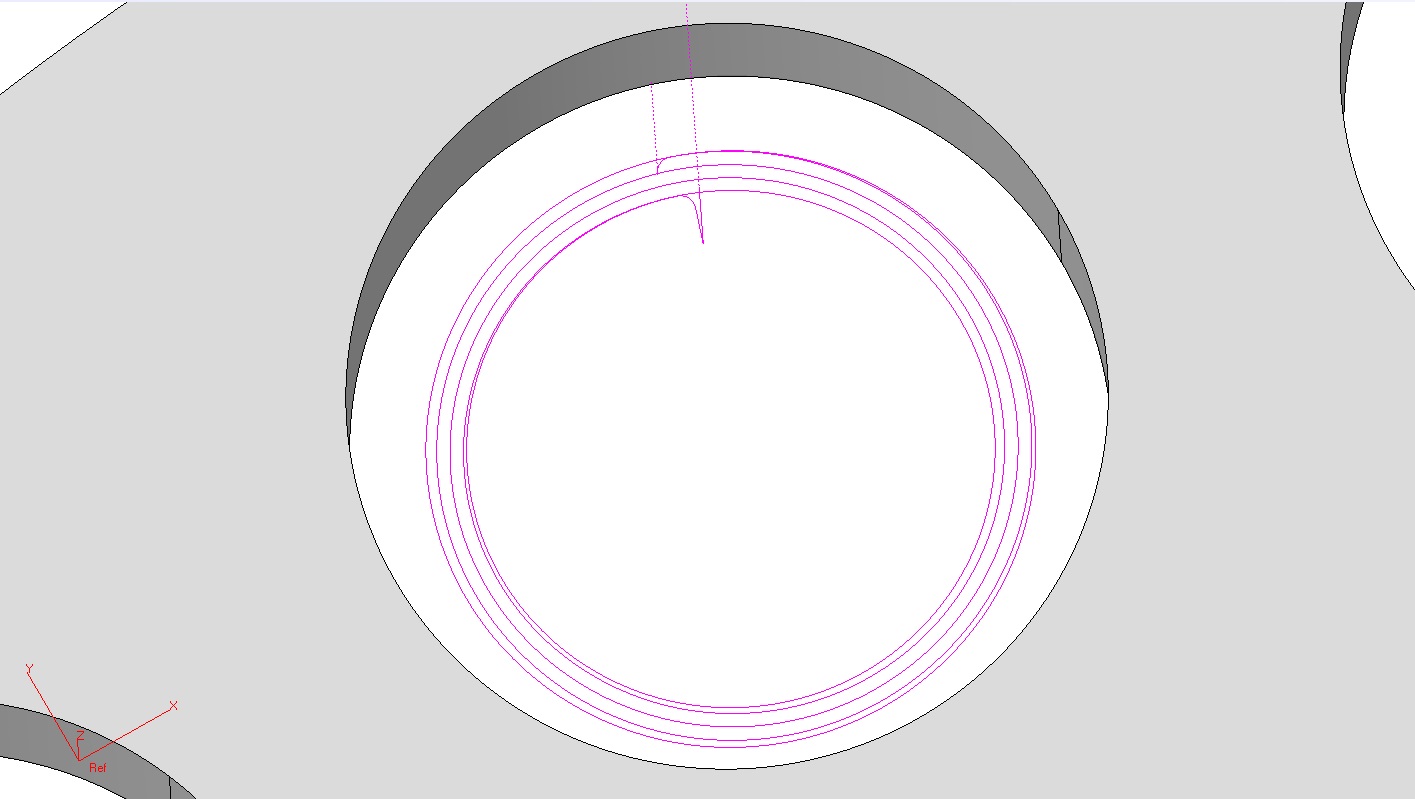
MILL / MILL-Pro / MILL Express – Helical Contouring with Multiple-Passes
Multiple-Pass toolpath type creates helical contouring toolpath for closed profiles using the new “Bi-Directional (open) / Helical (closed)” setting in the Contour wizard.
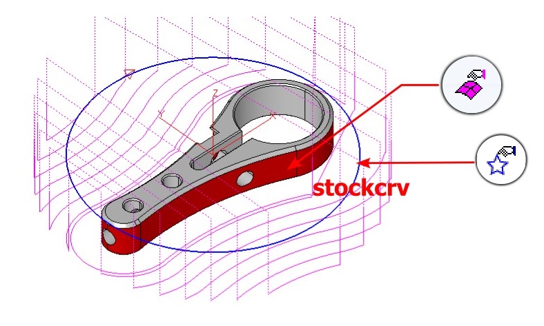
MILL / MILL-Pro / MILL Express – Contour Parallel Roughing with Stock Material
During Contour parallel roughing operations executed with the Multiple-Pass method, there could be instances of "air" moves, where the tool does not engage in cutting when working with stock material of a particular shape. To mitigate this issue, the latest version introduces a feature that enables the selection of a curve labeled "stockcrv" via the "Select Curves" command found in the Machining menu.
MILL / MILL-Pro / MILL Express – Contour Centerline
A "Contour (Centerline)" option has been introduced to the Face wizard, allowing the creation of a single-pass toolpath along the central line of the shorter sides of the model.
MILL / MILL-Pro / MILL Express – Curveless Contouring Depth Input
For Curveless Contouring toolpaths, which rely on the selection of the side walls of the desired profile, there may be instances where it is necessary to position the toolpath at a specific Z-level rather than at the profile's bottom. In such scenarios, users can include a "single" flat face in the selection of cut surfaces, and the system will utilize this face exclusively for depth calculation.
MILL / MILL-Pro / MILL Express – Curveless 4th Axis Indexing Automatic MCS Detection
The curveless toolpath engine now offers support for 4th axis indexing without the need for creating and selecting a Machine Coordinate System (MCS). In EZ-CAM, the origin of the World Coordinate System is taken as the reference point for indexing, and rotation angles are automatically computed based on the orientation of the chosen cut surfaces, as detailed below:
● When hole features are chosen as the cut surfaces, the system establishes the hole axis as the z-axis.
● If all selected flat cut surfaces share a common perpendicular normal vector, the system designates this direction as the z-axis. This category includes the bottom faces of pockets and top surfaces chosen for face-milling.
● When the selected cut surfaces are all parallel to a specific cutting direction, the system designates that direction as the z-axis. This applies to the side walls of through pockets and faces chosen for outside profiling.
● If the chosen cut surfaces do not meet any of the criteria mentioned above, the z-axis of the World Coordinate System remains as the default cutting direction.
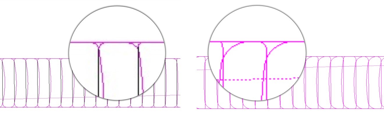
MILL / MILL-Pro / MILL Express – HSM Trochoidal Pocketing Enhancement
The High-Speed Pocketing toolpath strategy has been enhanced to incorporate larger-radius entry and exit moves into the cutting areas, enabling the utilization of faster feed rates without the risk of overtravel.
MILL / MILL-Pro / MILL Express – Hole/Fillet Diameter Display & Input
As we observed numerous parts being programmed, we recognized that the time spent checking hole and fillet diameters, along with manually inputting these values into their respective fields, was causing interruptions in the otherwise seamless workflow of the new system. To address this, we've made improvements to the double-click feature. Now, when you double-click on a face, it not only highlights the associated worksteps but also displays diameter information and copies this value to the clipboard and pastes it into the "value" field located on the right side. Furthermore, the hole wizard now includes a new button that enables you to conveniently use this value in the diameter field, like the functionality found in EZ-TURN boundary fields.
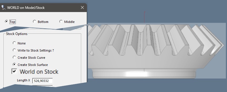
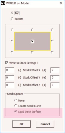
MILL / MILL-Pro / MILL Express – World on Model / Stock
The "World on Model" command has been updated and is now titled "World on Model/Stock". It introduces a new option that allows you to position the coordinate system on the stock boundary, rather than the part boundary. Additionally, a new feature has been incorporated, which enables the creation of a Stock Surface, enhancing this crucial feature.
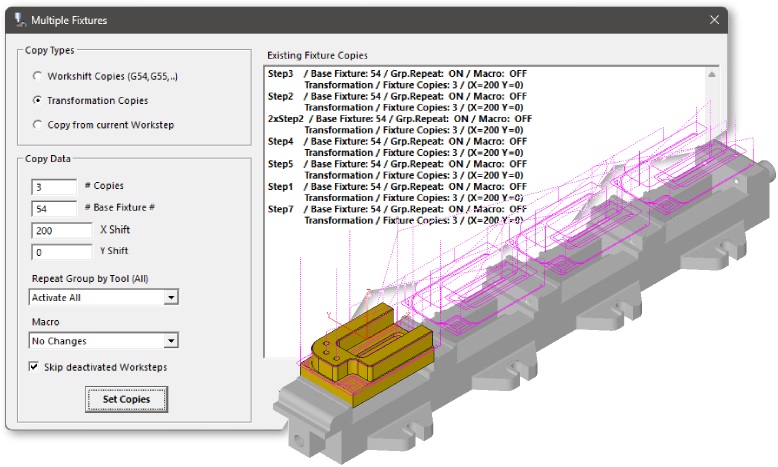
MILL / MILL-Pro / MILL Express – Repeat Manager
The Multiple Fixtures automation command has undergone a significant redesign, now serving as a comprehensive Repeat Management tool. You can either copy "Applied Repetitions" from the current workstep or manually input into the newly added X Shift and Y Shift settings and apply them to all active worksteps. Additionally, the "Delete Copies" function allows you to remove all repetitions from multiple worksteps with a single click.
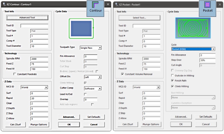
MILL / MILL-Pro / MILL Express – Milling Wizards New Design
The preferred approach for creating 2 ½ D milling worksteps has been to utilize the compact design of Contour, Face, Pocket, and Drill wizards. The latest version enhances their functionality by integrating additional crucial settings, eliminating the necessity to access advanced options. Users particularly appreciate the inclusion of a comprehensive set of tool parameters within the updated design layout.
TURN / TURN Express – Automatic Groove Detection
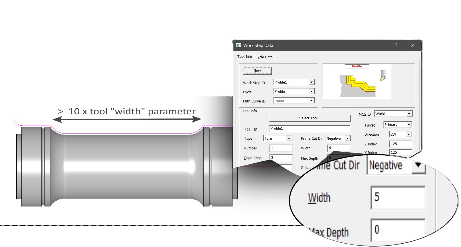
The recently introduced automatic groove detection feature generates toolpaths for groove regions suitable for the selected tool. This functionality supports various types of grooves, such as those on the outside, inside, front face, and back face. It's crucial to configure the tool parameters accurately, as the system avoids regions wider than 10 times the tool's width. To activate this new feature, ensure that you have not selected any cut surfaces. EZ-TURN operates in a fully automatic mode to detect enclosed groove regions within specified left & right boundaries or based on max-min Z limits of the model. If any cut surfaces are chosen, the automatic detection is disabled, and the system processes the profile of these surfaces as the groove boundary.
TURN / TURN Express – Skip Groove Option
The Skip Groove option has been revamped not to exclude regions wider than 10 times the tool width parameter. Previously, the tool width was exclusively enabled for groove tools, but it is now available for various tool types when Skip Groove is activated, allowing users to customize the limiting value as needed.
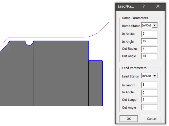
TURN / TURN Express – Profile Cycle Ramp and Lead Parameters
The profile cycle now includes support for ramp and lead parameters, akin to the EZ-Mill contouring cycle. This enhancement provides greater flexibility, enabling the extension of finishing passes at both ends to ensure safer entry and exit moves. Additionally, this new feature allows the toolpath to be extended to different limits beyond what is specified by the part boundary.
TURN / TURN Express – Collision Detection
The new curveless system now includes collision detection for the connection moves between consecutive worksteps. It automatically generates safe travel paths, eliminating the need for manually creating single point curves to define start and end locations.
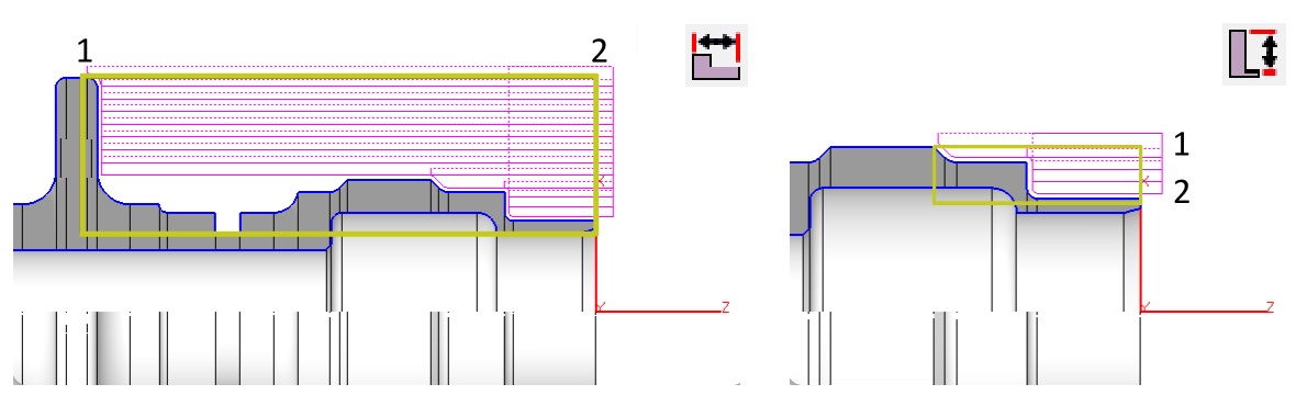
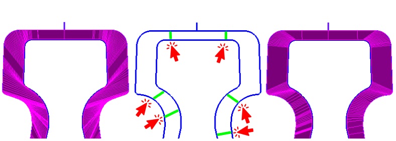
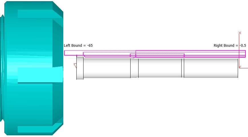
TURN / TURN Express – Left-Right and Outer-Inner Boundary Settings
The new template system is specifically designed to minimize manual data entry in the dialogs. As a result, two additional commands had to be incorporated into the Turn Machining tab. These commands are meant for configuring the Left-Right and Outer-Inner boundary settings, which are of utmost importance for the curveless system. Both commands enable users to make graphical selections using point snap options, simplifying the process. The section geometry elements are highlighted in a bold color when the 3/4 section view is activated, making it especially helpful for this purpose.
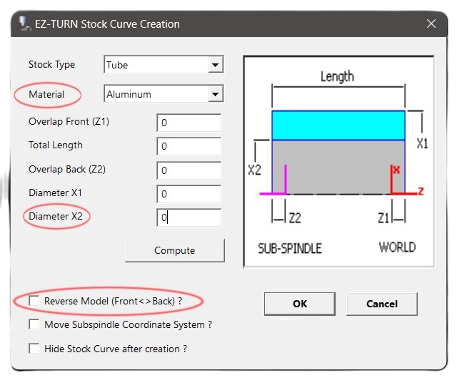
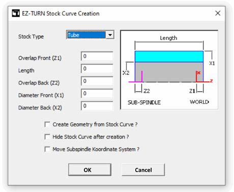
TURN / TURN Express – Stock Curve Creation
When importing or transferring solid models in EZ-TURN, the software now includes an automatic process to detect the turning axis and origin point placement. If the automatic placement selects the incorrect side of the part, the new "Reverse Model" option within the "Stock Curve Creation" window can be employed, streamlining the procedure, and eliminating the need for manual adjustments to the origin and world coordinate system orientation.
You will also notice the Compute button in Stock Curve Creation assigns the inner diameter value of the model to the “Diameter X2” field to be used for correct drill size, etc. or to define a “tube” type of stock more easily.
TURN / TURN Express – New Template Management
Template support for individual cycle types is now accessible across all mill, turn, and turn-mill machining wizards. Stock material selection can be made either during Stock Setup or in Stock Curve Creation, offering users the flexibility to work with different sets of template files.
These templates, specific to the chosen material, are stored in folders labeled "WorkstepTemplateMetric" followed by the stockMaterialIndex, such as "WorkstepTemplateMetric," "WorkstepTemplateMetric1," "WorkstepTemplateMetric2," and so forth.
Users have the option to edit the templates that come pre-installed with EZ-CAM setup or create new templates by utilizing the "Set Defaults" button available in every wizard. The Workstep ID prompt now includes a new list box for template selection, along with "Delete" and "Rename" buttons, facilitating more efficient template management.
Settings for the currently selected template in the list box are displayed in disabled fields within the data dialogs. You can easily navigate through the list and select the appropriate template before clicking "OK" to create the desired operation.
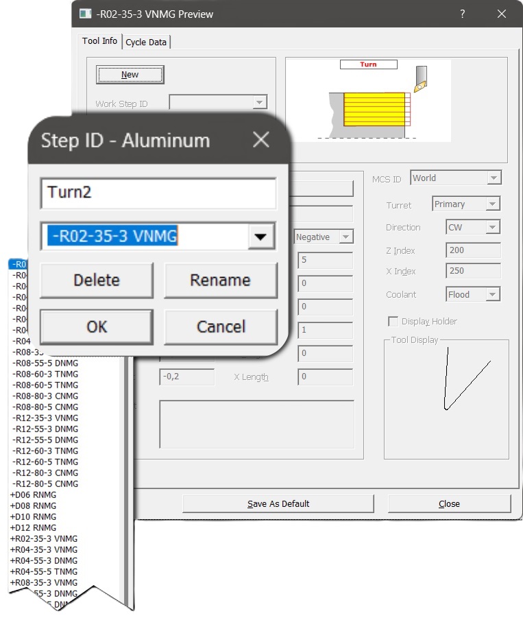
This method is highly recommended for creating worksteps that are ready for toolpath generation after simply selecting the cut surfaces.
EDM – New Match XYUV Curves
Match XYUV Curves command in the Curves menu facilitates the creation of line entities that match sections of upper and lower path curves. When the edge geometry of the solid model cannot provide a precise match, this new command offers a much more straightforward approach for manually creating line entities to define the missing connections, thanks to the special functionality of snap to screen.
EDM – Die & Punch Wizards Path Directions
The Die and Punch wizard now examines the path directions of the selected curves, ensuring that it generates wire paths on the appropriate side of the part while producing G41/G42 output that matches this orientation.
EDM – Die & Punch Wizards Thickness Calculation
The Die and Punch wizards now calculate the default value for "thickness" with the correct positive or negative sign based on the curve z-levels and the top and bottom limits of the solid model.
March 2023:
Ez-Cam 2023 - Is here.
What’s new in EZCAM Version 2023
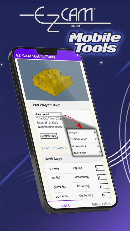
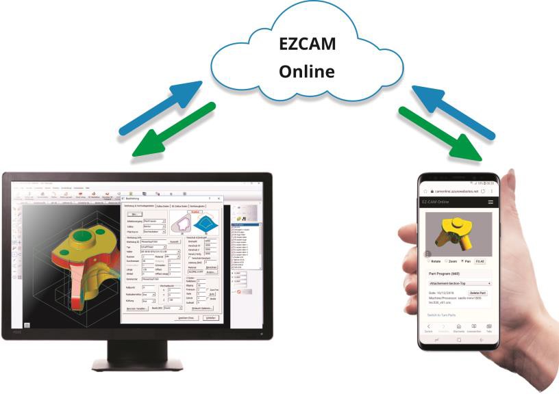
EZ-CAM Mobile Tools for Remote Control
EZ-CAM now offers a free companion app for mobile devices. Whether at your machine or away from your office, with the new EZ-CAM Mobile Tools app you can view, simulate and change your EZ-CAM program directly on your mobile device and then download the changes back to your PC.
Google Play: https://play.google.com/store/apps/details?id=com.ezcamandroid
iOS: http://ezcamonline.azurewebsites.net/Account/Login
● In EZ-CAM 2023, load or create a part.
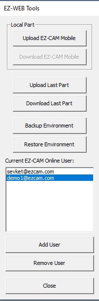
● Then, from the “Machining” menu, select first “Verify All” and then “3D Preview” and then “EZ-WEB Tools”.
● Select an EZ-CAM online user account from the list of users (or add and select a new user ac-count via the “Add User” button).
● Click “Upload to EZ-CAM Mobile” to upload the currently loaded part to the selected user account.
● In EZ-CAM Mobile Tools on your mobile device, select “Refresh” from the ellipsis menu to view and edit the newly uploaded part in the “Data” tab – or play a preview of it in the “Simulation” tab.
● When you’re done making changes to your part in EZ-CAM Mobile Tools and are ready to update it on your PC, return to EZ-CAM and, with the same part loaded, click “Download from EZ-CAM Mobile” in EZ-WEB Tools.
● The newly added G-Code tab can be used to check and export G-Code from your mobile device to your CNC machine tool via USB stick.
EZ-TURN Curveless Lathe Programming
When solid model is available all turning cycles can now be operated by selecting Cut Surfaces rather than working with path curves. This new method allows faster and errorless program-ming with the help of its following features:
● System automatically use all visible surfaces by default which works well for all cycle types except groove and thread requiring partial selection via Select Cut Surfaces com-mand.
● When selecting faces inside the part the new 3/4 Section View command can be utilized.

● The new option in cycle data enables the face, bore and profile cycles to skip the groove regions without requiring any geometry work.
● Turn, Face and Profile cycles now work well within the defined Left and Right Boundary settings by automatically extending and/or trimming the region selected for machining.
● Face Profile cycle now respects the limits defined by Outside and Inside Boundary Set-tings again to eliminate any geometry/curve creation.
● Drill cycle detects stepped holes and sets the Depth parameter according to the selected tool size.
EZ-MILL Curveless Programming Enhancements
Solid models have dominated any other form of communication between CAD engineers and EZ-CAM programmers. To benefit from this exchange, beginning with v2021 EZ-CAM has shifted its focus from the traditional approach of requiring curves, which define a path or boundary for each workstep, by moving away to a more sophisticated solution that requires clicking on the model's features. In doing so, Smart Click can create worksteps in the same time it takes to rec-ognize a hole, chamfer, fillet, pocket, or contour.
Facing: Select the stock as a Check Surface and include the entire model as Cut Surfaces.
Drilled holes: Select one hole, and all holes that have the same attributes are grouped into one workstep.
Chamfers and Corner Rounds: Select a surface in either of these two categories, and all the surfaces that make up that feature are connected to create one workstep.

Pockets:
● Closed pockets—are created by selecting the horizontal surface at the bottom, and if there are any islands, they are avoided automatically.
● Open pockets—are created by selecting the bottom surface of a pocket with missing walls. EZ-CAM will detect these open regions to permit the tool to strategically start out-side these boundaries while applying the necessary tool overlap.
● Thru pockets—are created by selecting a vertical surface of a baseless pocket. EZ-CAM will chain all adjacent surfaces to form a closed boundary. Thru pockets provide an addi-tional tool depth that can be adjusted or removed in EZ-CAM's .ini, configuration, file.
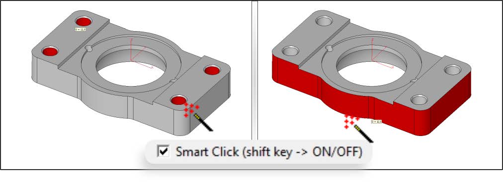
Contours:
● Machine the outside perimeter of a part by selecting the entire model.
● Closed contours are created after selecting one vertical surface, allowing EZ-CAM to chain the entire closed boundary.
● Open contours are created by selecting one vertical surface, where chaining occurs from beginning to end. Turn Smart Click off (toggled by the shift key) to add or remove sur-faces from the chain.
Special Curveless Features:
● SmartClick performance has been greatly increased even for very large models.
● Double click on a surface hilites all worksteps with this surface selected as cut surface.
● “Combine Regions” option is added to the Pocket wizard to machine the boundary merged from all selected faces at the top z-level.
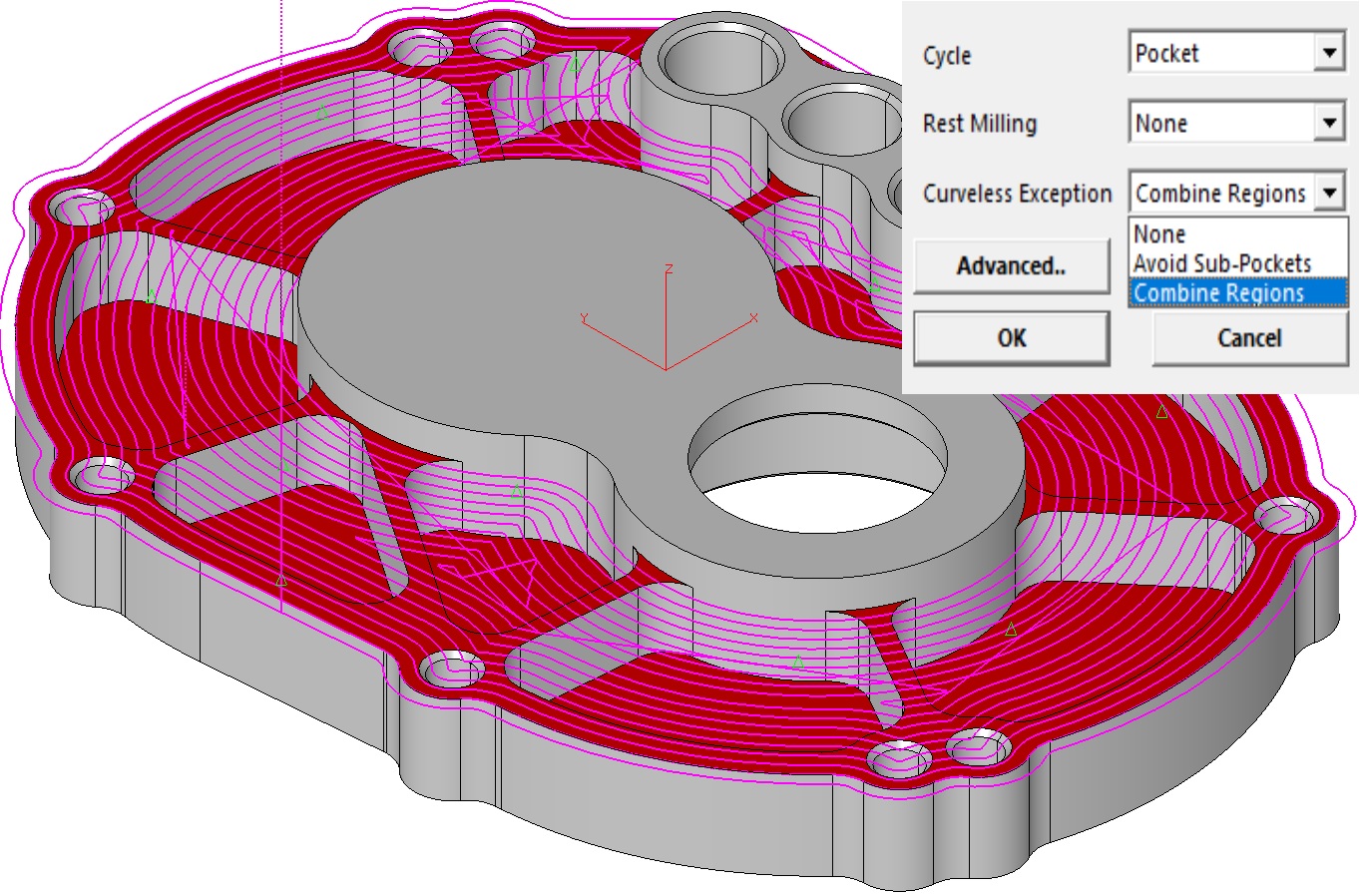
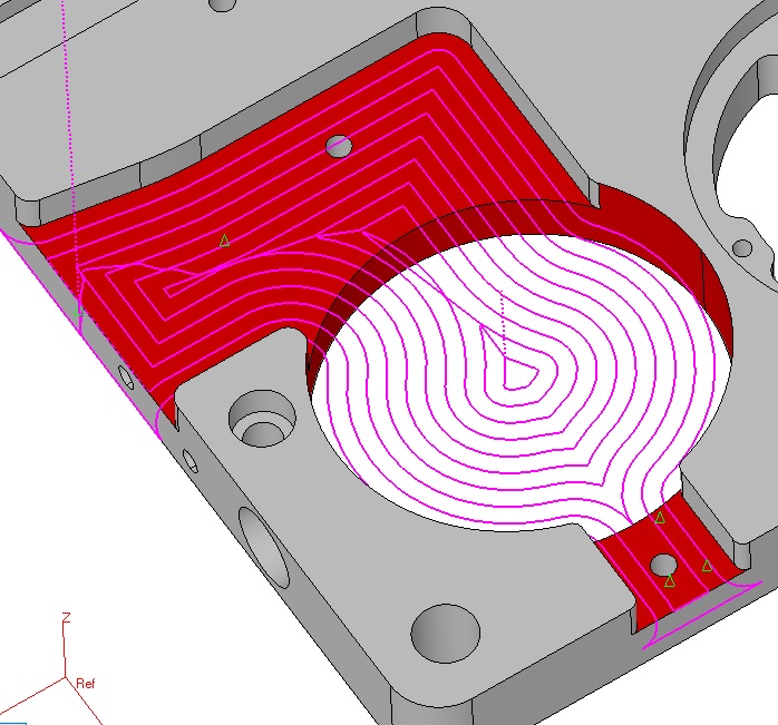
● “Avoid Sub-Pockets” option is added to the Pocket wizard to skip machining cut-out regions.
● 4th axis pocketing & contouring now support Curveless method without MCS creation. One workstep needs to be defined for each angle which is computed from the selected cut surfaces, so user can skip MCS creation and selection steps. This feature should help all 4th axis cases where MCS would have been defined at world origin.
● Curveless contouring has been further enhanced to support all cases for sidewall finish-ing and ignores offset direction to create toolpath per climb milling setting only.
● Open Through pockets can be processed by selecting side faces only.
● Stock Surface support for pocketing and contouring.
● Curveless milling supports check surfaces to be avoided.
● Support for Draft angle with upper fillet has been added.
● Start point can be defined using single point curve selected as the only check curve.
● Open Edge pocketing selects first plunge outside the stock if possible.
● Open Edge pocketing checks for gouges and adjusts toolpath extension offset.
● Curve Wizard renamed as Machining Wizard supports Curveless method by shared cut surfaces.
● Turn-mill cycles support Curveless method eliminating the need to create path curves.
EZ-MILL Pro 3D-Wizard Enhancements
● Constant-Z finishing produces toolpath also for isolated vertical faces.
● Equidistant 3D finishing strategy has been much improved to handle all flat regions in complex models within single workstep.
● 3D-Roughing includes now the newly added "Helical" option.
● Constant-Z Finishing includes the new step type "Zig Zag" to avoid rapids when machin-ing open surfaces without climb milling requirement.
EZ-MILL Helical Pocketing Enhancement
Major improvement in Helical pocketing enables boundaries with multiple collapse regions to be machined using single workstep.
EZ-EDM Pocketing includes Finishing
EZ-EDM multi cavity pocketing adds finishing defined by “No Passes” after pocketing wire path.
EZ-MILL Express EPS Import
EZ-MILL Express loads EPS file as single curve which then can be selected as the workstep path using “Select Curves” command.
EZ-MILL Express Template Support
"From Template" command is added to the Workstep menu. When creating worksteps user can create templates using the newly added "Set Defaults" button on the wizard dialogs.
Change Cut Surface Colour
The new “Change_Cut_Surface_Colour” command in Help-Toolbox which has also been assigned it to F1 key displays faces selected by all worksteps in yellow color. At any time user can click on F1, inspect yellow regions and then Undo.
Create Stock Surface
“Create Stock Surface” option has been added to the “World On Model” command dialog to make the it more compatible with Curveless machining.
Alibre – EZ-CAM Integration
Alibre-EZCAM associative connection enables updating toolpaths easily. After each model change in Alibre, user selects only “Alibre Update” & “Verify All” commands to create the new toolpaths.
July 2021:
Ez-Cam 2022 / V29 - Is here.
What’s new in EZCAM Version 2022 (V29)
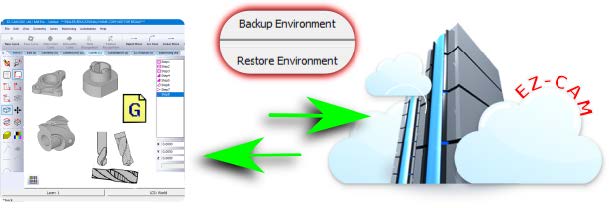
Back up Everything with the Click of the Mouse
Now you can back up your files and settings to the EZ-CAM cloud, such as post-processors, tool library, recent programs, toolbars, and your custom interface–all with the click of the mouse. It is just as easy to retrieve your files and settings on any pc using “Restore Environment”.
Your Video Speaks More than Words
For support questions, you can record your screen and add narration. EZ-CAM saves an avi file that you upload to the cloud for immediate review. Recording your screen shares the same value as the instructional video EZ-CAM sends to you in return.
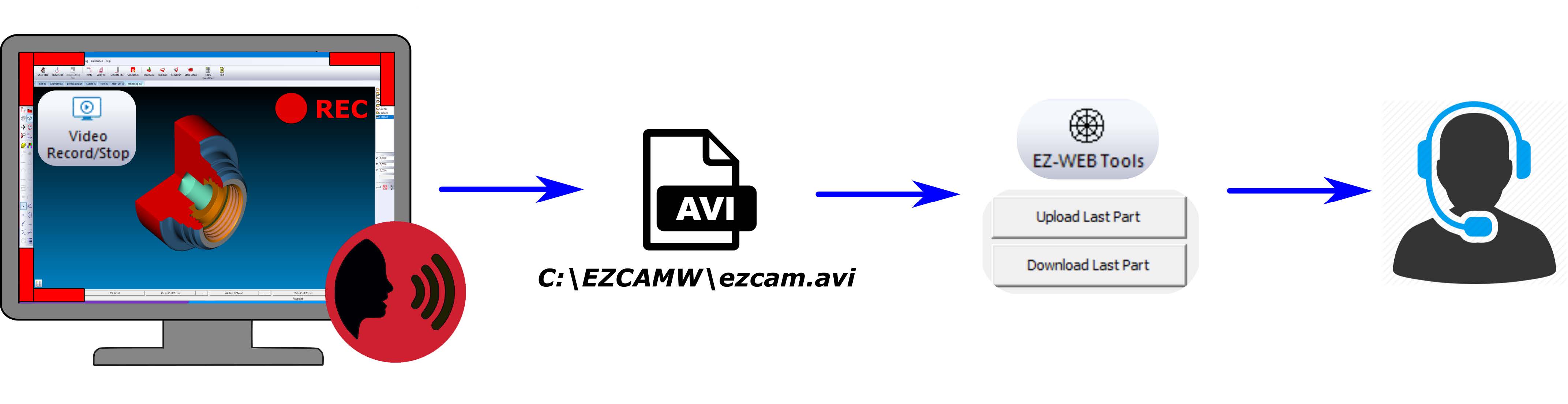
When You Need Support
Back up your environment, and share the email address you used to register. We will examine your part files, post-processors, and avi file to fulfill any request. Your uploaded files will lessen the number of emails and time spent with support. And, for crystal clear communication, our responding emails may include graphics and video links.
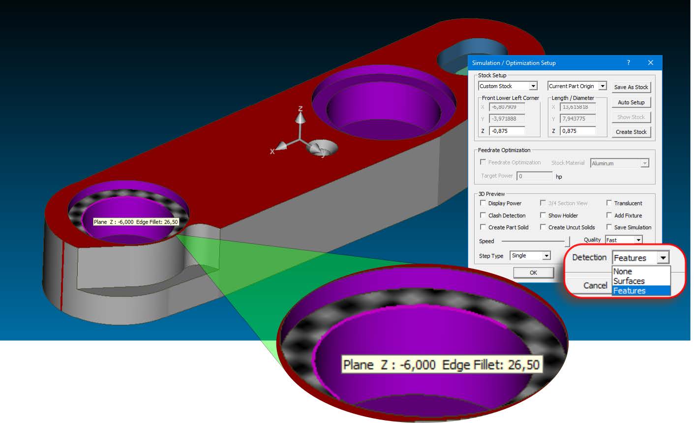
New Simulation Engine with performance boost includes Feature and Workstep Detection
● 3D Preview speed is increased 2-10 times depending on the model and tool properties.
● Feature detection with pop-up dimensions such as diameter, fillet radius, chamfer angle and plane coordinates allows the user to effectively check for programming errors.
● Machine coordinate system is displayed by clicking on any face of the simulated model and the workstep that has last touched this face is selected to let the user check/edit its programming parameters.
● Rapid Cut resolution is increased by 100% for all quality levels.
● Undercut/Overcut material display can now be dynamically rotated and zoomed without having to use the Recall Part command.
Curveless 2,5D Machining by selecting Cut Surfaces to define the Path
When solid model is available all 2,5D milling cycles can now be operated by selecting Cut Surfaces rather than working with path curves. This new feature allows faster and errorless programming since critical parameters such as z-data, draft angle and toolpath direction are automatically derived from the solid model.
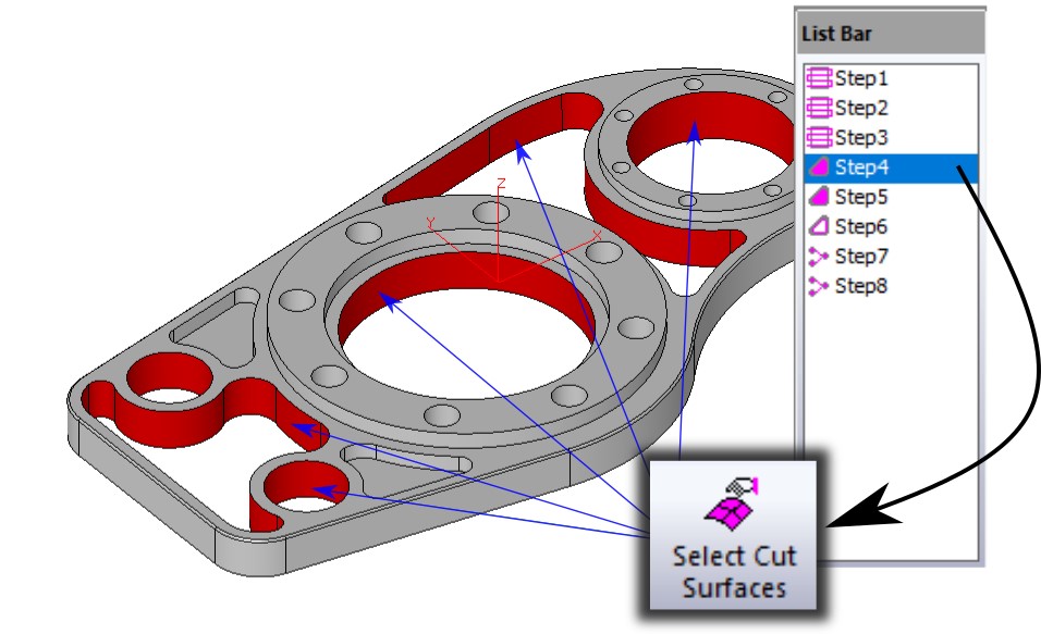
New Smart Click option to fast select Cut Surfaces
When Select Cut Surfaces command is selected the new mouse icon is activated to show that Smart Click mode is ON. In this new mode you can select all the bounding side faces with a single click much like chaining geometry to create path curves. For drill cycles Smart Click uses the diameter and depth data of the selected hole to add other holes with same parameters automatically. Curveless machining and Smart Click make powerful companions offering high level of automation. When needed Smart Click can be deactivated/reactivated by pressing the shift key.
EZ-CAM and EZ-CAM Express now share the same newly designed 2,5D cycle wizards
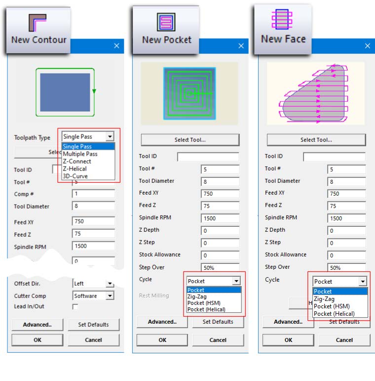
Worksteps created by the “Contour”, “Pocket” and “Face” wizards can now be edited using the same dialogs as in creation. Contour wizard includes the new Toolpath Type list box and Pocket/Face wizards include the new Cycle list box to eliminate navigation to cycle data for lengthy customisations.
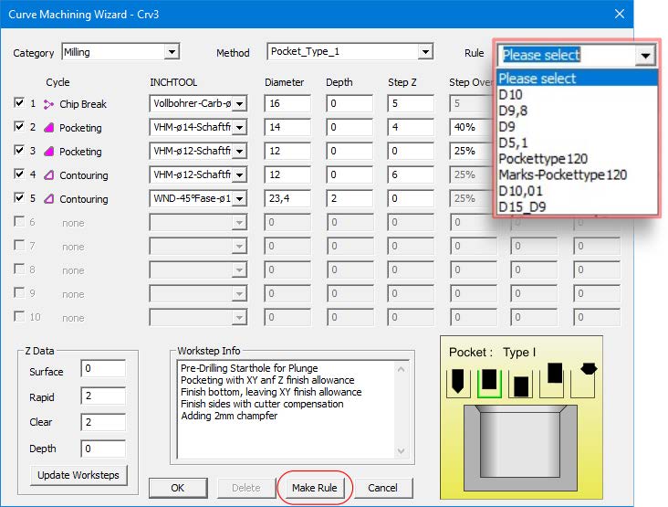
Curve Wizard’s Make Rule feature supports save-delete-rename functions
The Make Rule button adds a new rule which associates the current curve name with the selected method to the list box at the right top corner. Any list box entity can be renamed or deleted by first selecting and then typing directly into the edit field. When the curve wizard is activated for a curve whose ID starts with the name of the rule its associated method is selected automatically.
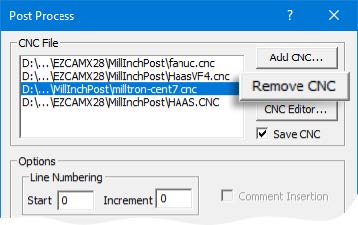
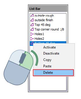
New "Remove CNC" button in Post Dialog
"Delete" is added to the new right-click popup in the workstep listbox
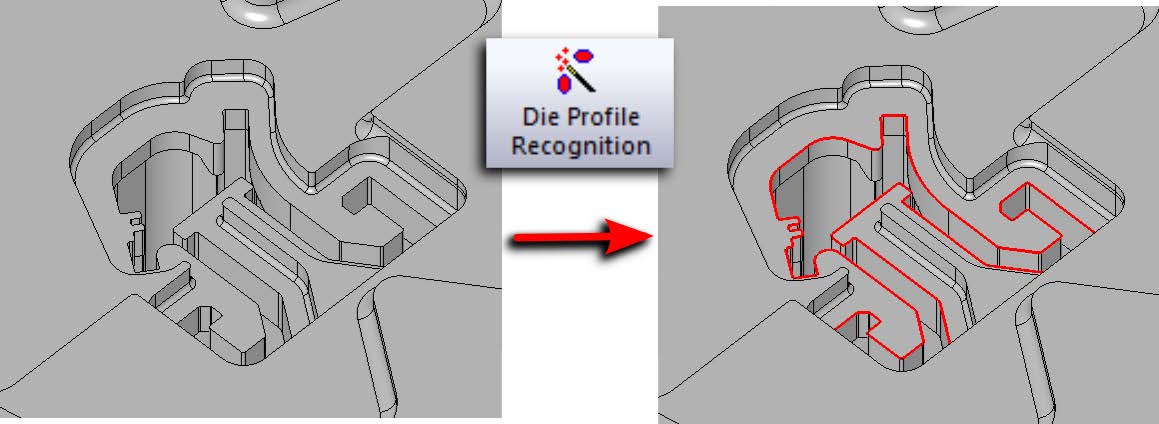
New EZ-EDM command to recognize die profiles in the solid model as curves
When solid model is available path curves can be easily created by the new Die Profile Recognition command. These curves are highly accurate and can be selected by Die Wizard after only applying Autostart For All Curves command in the Automation menu.
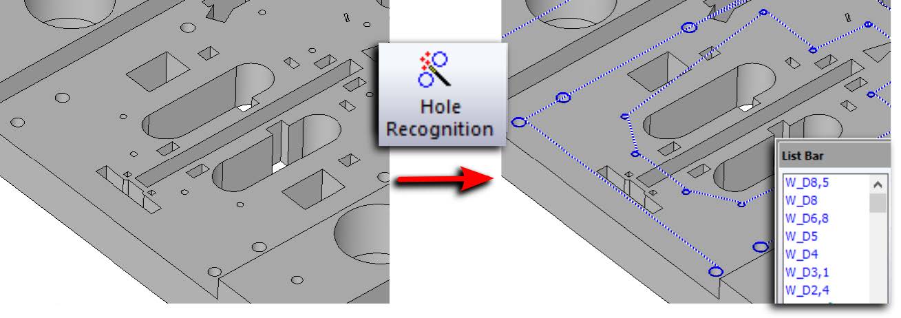
New EZ-EDM command to detect holes in the solid model as curves
When solid model is available path curves connecting the holes can be easily created by the new Hole Recognition command. Each curve ID displays the diameter of its included holes. Maximum Hole Radius threshold can be customized using the following ezcam.ini setting:
[EDM]
maxHoleRadius=
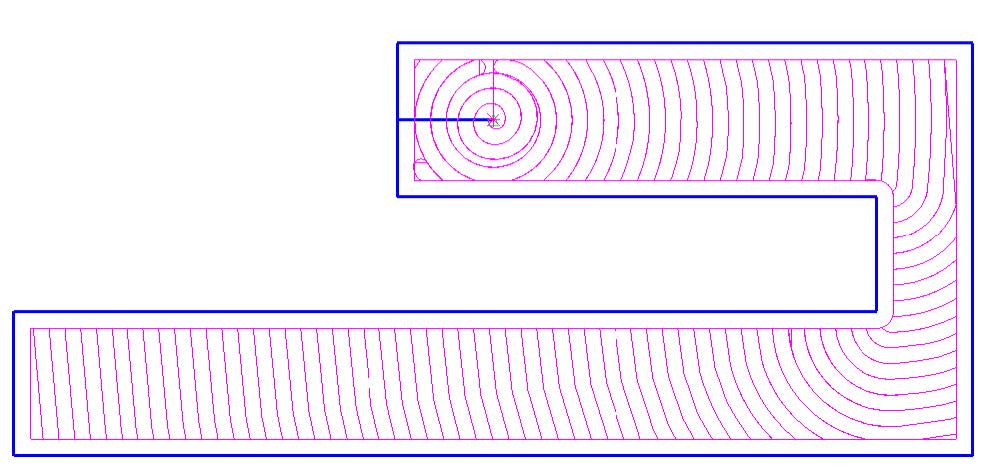
New Destruct Pocketing cycle in EZ-EDM avoids rapids and returns to the start point
Radial (HSM) and regular pocketing as well as zig-zag wire paths avoid rapids by making the connections between separated regions along the pocket boundary making sure no solid body splits and falls onto the table. After finishing pocketing, wire returns to the start point again moving safely along the boundary path.
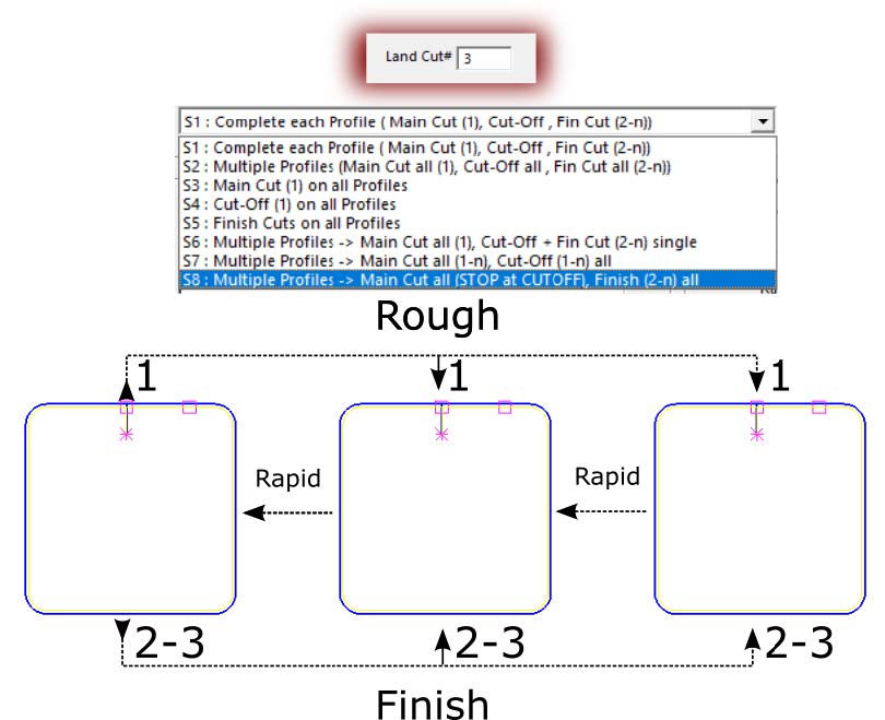
New DIE method S8: Multiple Profiles → Main Cut All, Finish (2-n) All
Popular Die Wizard in EZ-EDM gets one more Strategy added to apply single roughing pass with STOP and CUTOFF followed by 2-n finishing passes. Roughing uses the first row of the technology data and the finishing passes use the subsequent rows.
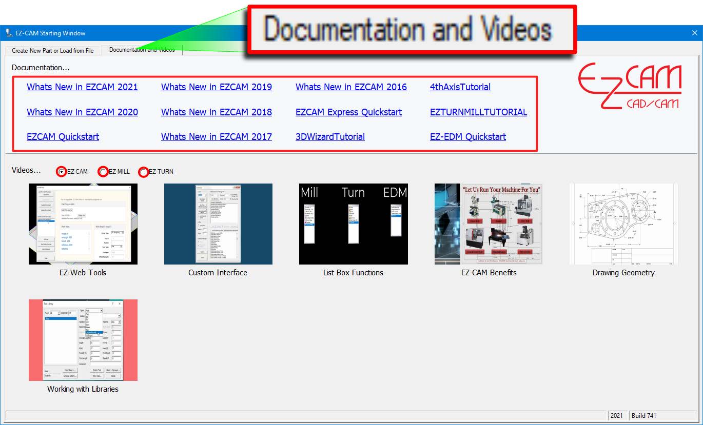
Starting Window has a new tab displaying helpful PDF documents and product Videos
September 2020:
Ez-Cam 2021 / V28 - Is here.
What’s new in EZCAM Version 2021 (V28)
CAD Integration – New SOLIDWORKS ADD-IN
Following the great success of the ALIBRE CAD Add-In introduced in EZCAM V2020, we decided to improve EZCAM’s CAD connectivity by creating a similar direct Add-In for the leading SOLIDWORKS CAD System.
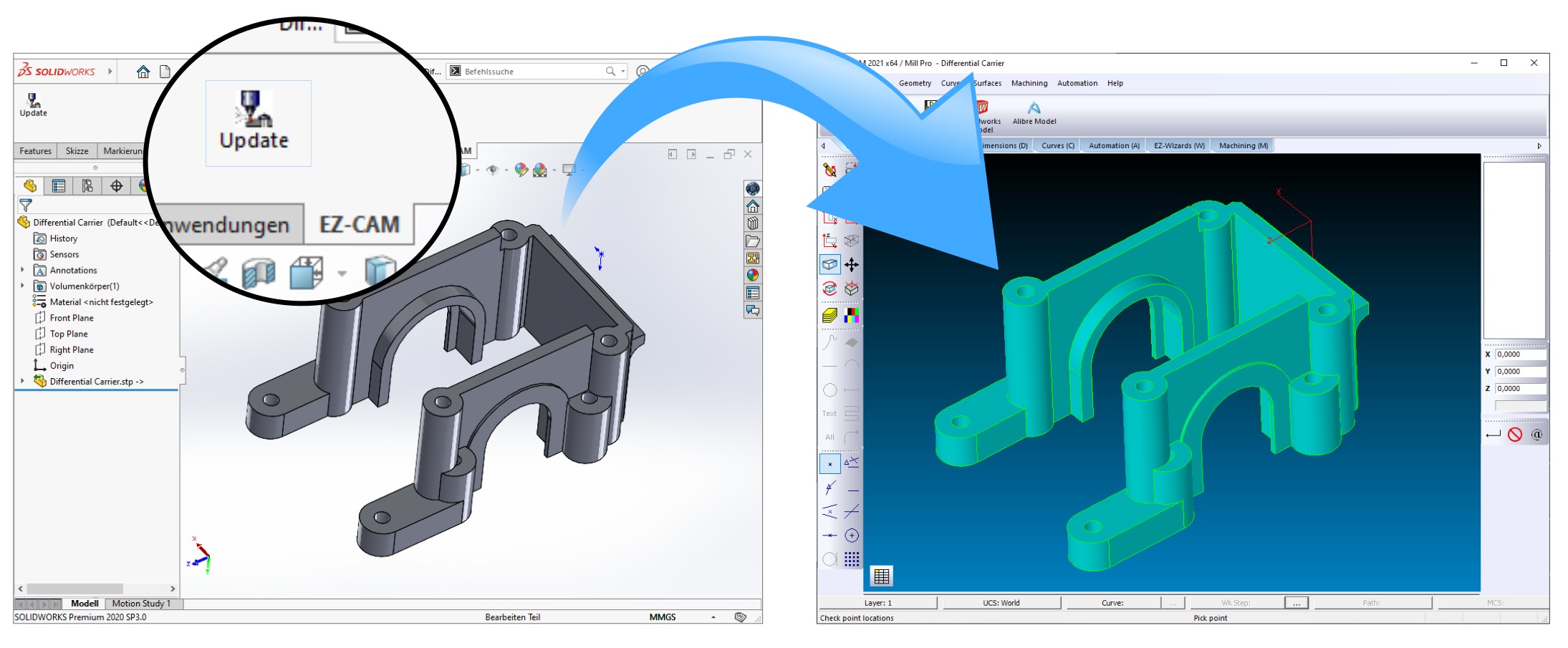
When single-clicked, the new plug-In command instantly transfers the model from the current Solidworks session into the active EZ-CAM module. Blanking unnecessary bodies inside Solidworks beforehand enables the user to transfer only the selected parts of an assembly. The new release installs the Add-In automatically if a local Solidworks installation is detected.
EZCAM’s already existing “Update Solidworks” command has also been improved. It now automatically transfers each part of a Solidworks assembly into a new EZ-CAM layer with ID=part name. Of course, EZCAM itself has been updated to also load Solidworks v2020 files (*.SLDPRT) via its regular “File Open” command.
CAD Integration – Updated ALIBRE ADD-IN
The existing EZCAM Alibre Add-on module has been further optimized for quick model update after every modification in the active Alibre session. The Add-on’s “Transfer” command instantly transfers each part in the assembly into a new EZ-CAM layer with ID=part name. Further part selection in EZCAM is then easily handled via the “Layer Manager” introduced in EZCAM release v2020.
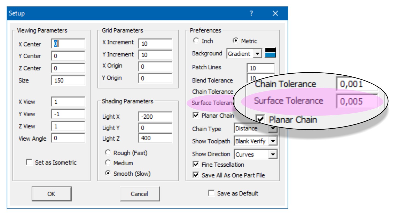
CAD Integration – New 3D Surface Import Setting - “SURFACE TOLERANCE”
The new “Surface Tolerance” setting in the “View / Setup” dialog allows the user to specify the tessellation quality of the model imported from CAD files according to his machining tolerance needs. This setting is also applied to models directly transferred from the Alibre and Solidworks session using their EZCAM Add-In’s. By default this setting is set to 0,01 mm in metric or 0.001 for inch mode.
MILL-Pro – 3D Wizard – Constant-Z Finishing - New “Retract to Z-Clear” Support
The “Constant-Z” finishing method has been updated to support the “To Clear” option located on the “Advanced” machining dialog (see “Tool Info/Z-Data” section). In combination with the “Step” option set to “Rapid”, the system only retracts to Z-Clear distance above each Z-level before performing XY axis rapid move to subsequent plunge location. Of course, this is only done if there is no collision with the part along this move. In all other cases, the system retracts to ZRapid level for safety as usual. This option saves precious machining time by avoiding long distance retract & plunge moves.
MILL-Pro - 3D Wizard – New “ZIG-ZAG” Link Type (ex. “OPEN SURFACE”)
The "Open Surface" link type in 3D-Wizard's “Constant-Z” finishing method has been renamed as "Zig-zag" and now can be successfully used for all tool types, including undercut tools, to shorten the machining time by eliminating rapid-over moves between consecutive z-cuts.
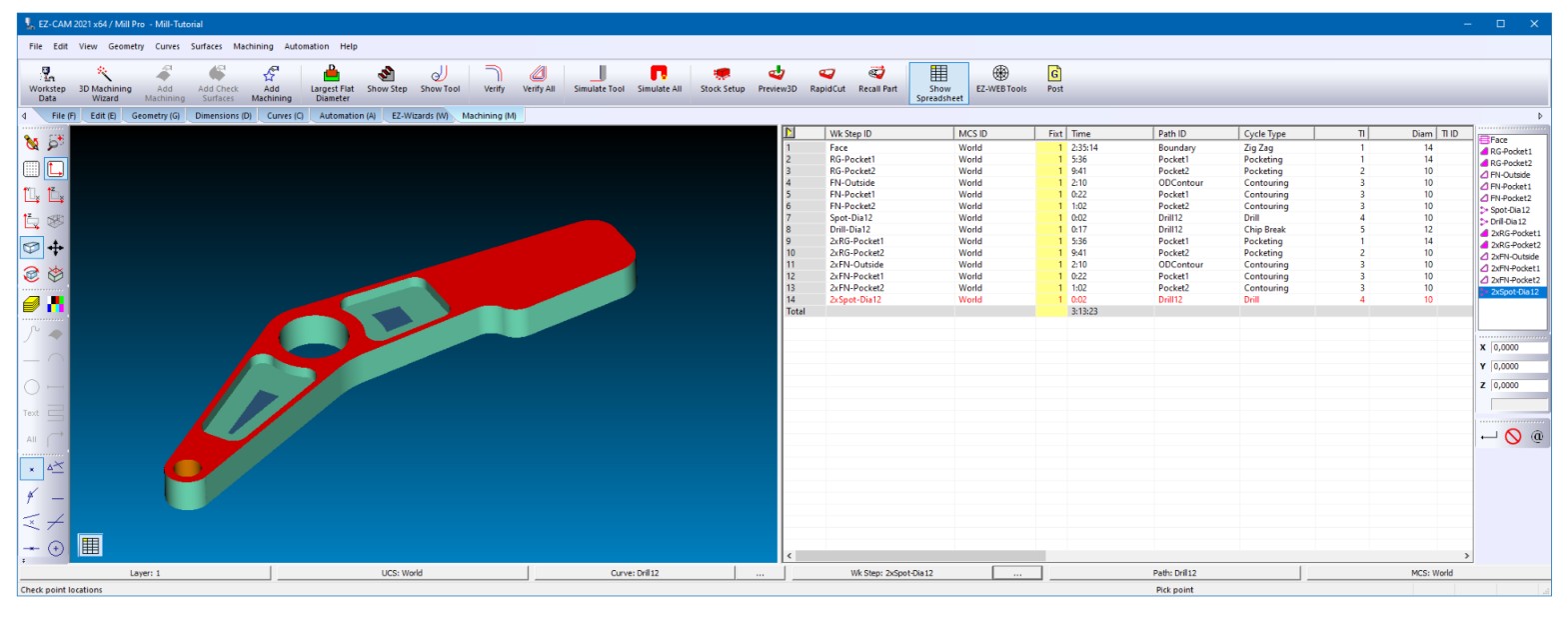
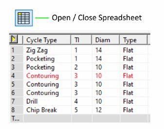
MILL / MILL-Pro / TURN – New SPREADSHEET Option – Docked to Right Side
A new option “Dock Spreadsheet to right” in the “View / Customize” dialog allows the commonly used “Spreadsheet” to be docked to the right side of the screen. With the help of this new feature, users can make better use of wider screens and keep the Spreadsheet always visible on the right side. Of course, as an alternative, the spreadsheet can still be made floating and then moved to a second screen instead.
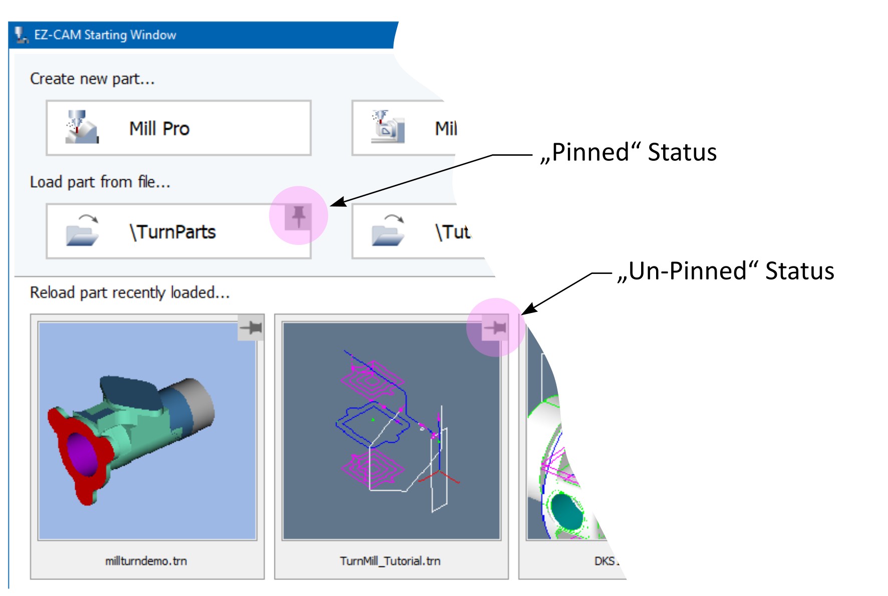
MILL / MILL-Pro / TURN – New PIN-DOWN Feature for Startup Window
While the “Pin” down feature in startup window has already been available for the recently loaded part files, it has now been added to the four “Folder” buttons as well. This allows fixing the display of the most frequently used folders to have them readily available.
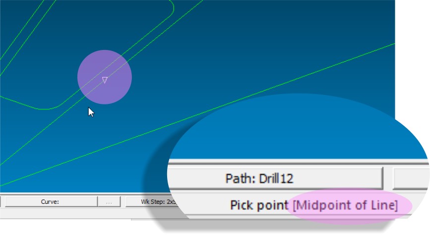
MILL / MILL-Pro / TURN / EDM – Current SNAP-MODE Status Display
The “Snap” mode used for the currently snapped location on the screen is displayed in the status bar’s right side message area, e.g. "Pick point [Midpoint of Line]". This new feature is especially helpful when the snap mode is set to one of the multi-type settings such as “Snap All”.
MILL / MILL-Pro / MILL Express – Updated & Enhanced 2.5D Machining Wizards
Worksteps created by the “Contour”, “Pocket” and “Face” wizards can now be edited using the same wizard dialogs. Of course, the full set of parameters and settings are always available via the “Advanced” button. The new “Select Tool” option provides access to EZCAM’s tool library, while additional toolpath and cycle options ease the usage of EZCAM’s various toolpath combinations.
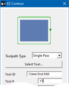
EZ-Contour Wizard
New - “Toolpath Type” Option
Single Pass : Creates a single pass along the profile
Multiple Pass : Creates multiple parallel passes along profile
Z-Connect : If a Z-step is defined, this option connects the step passes resulting in a back and forth cutting process
Z-Helical : The tool continuously plunges down along the profile until Z depth or Z step is reached
A complete pass is generated at the end at final depth
3D-Curve : The tooltip exactly follows curvature of a 3D curve
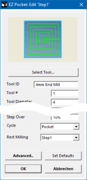
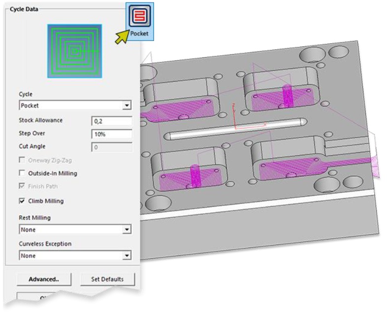
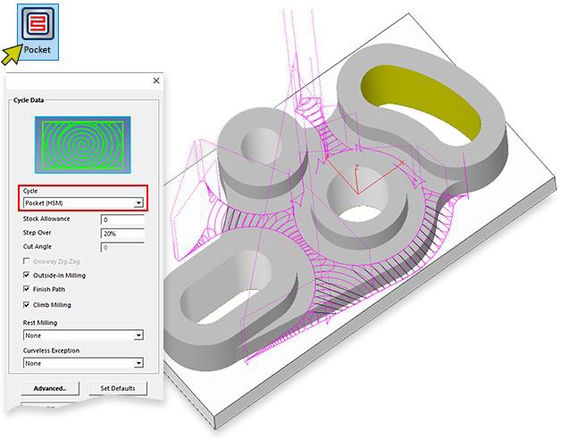
EZ-Pocket Wizard
New - “Cycle” Option
Pocket : Creates contour parallel roughing passes
Zig-Zag : Creates Zig-Zag type, back and forth passes
Pocket (HSM) : Creates HSM arc type high speed passes with constant volume removal control
Pocket (Helical) : Creates continuous adaptive stepover passes resulting in a kind of helical toolpath
New - “Cycle” Option
This option lets you select a previously created pocketing workstep.
The new workstep then tries to remove as much of the remaining material as possible by using a smaller tool
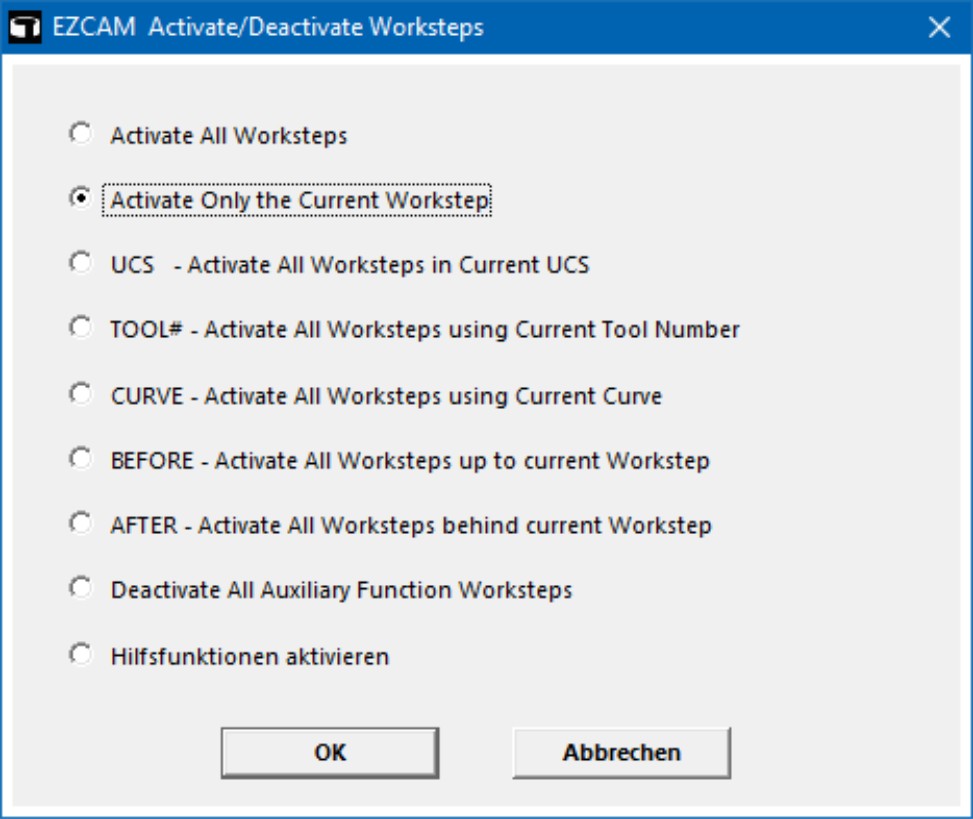
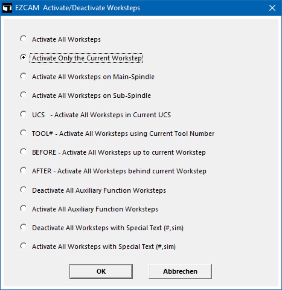
MILL / MILL-Pro / TURN – Fast ACTIVATE / DEACTIVATE Worksteps
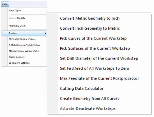
A new “Activate-Deactivate Worksteps” macro has been added to the “Help” menu “Toolbox” list. This macro allows single-click activation or deactivation of worksteps based on certain rules. For example - one can deactivate all worksteps below the one currently selected. This is often used when only certain worksteps need to be verified or simulated. In TURN mode you can also deactivate all sub-spindle worksteps for posting main-spindle work only. These are just some examples. Please note that such macros can also be assigned to certain function keys (F1-F12, via “EZCAM.INI” settings) for faster access.
EZ-MILL / MILL-Pro EZ-TURN
MILL / MILL-Pro / TURN / EDM – TRANSFORMATION Commands for WORLD System
It is now possible to apply any of the transformation commands (Translate, Move, Rotate, etc.) directly to the “WORLD” coordinate system. This offers another flexible method to set the main part origin. Please note that the “All” select command does not select the WORLD system which can only be selected from the list box on the right side of the screen. Alibre and Solidworks model update commands recognize the new origin set by this new method.
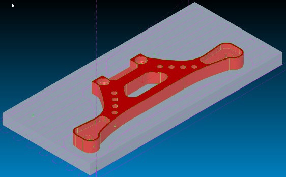
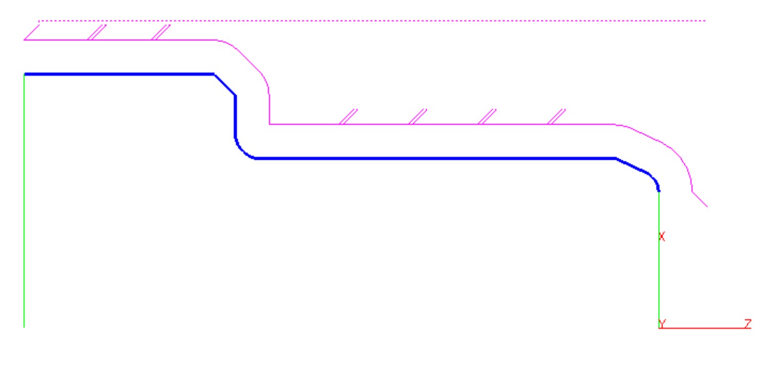
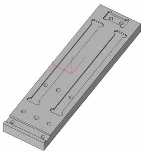
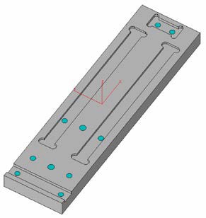
MILL / MILL-Pro – “CURVE CHAIN” Command Updated
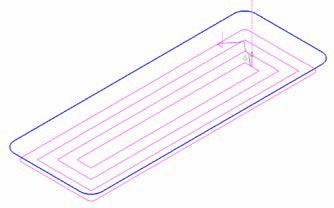
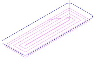
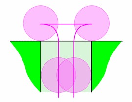
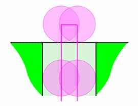
When manually chaining circle entities into curves, the system now checks if the connection at Z-Clear would cause collision with any of the visible surfaces. If the connection between two circles at “Z-Clear” default level would cause a collision, the circles are connected using a rapid curve link, otherwise the connection link will be of linear type. Such rapid curve links make the toolpath to retract to “Z-RAPID” level above the surface before continuing to the next hole to be drilled. Please note, that in order to make use of this new feature, the "Rapid Mode" curve command needs to be set to “Off” ( = Linear link if possible ). Otherwise all curve links will be of the type “Rapid” automatically.
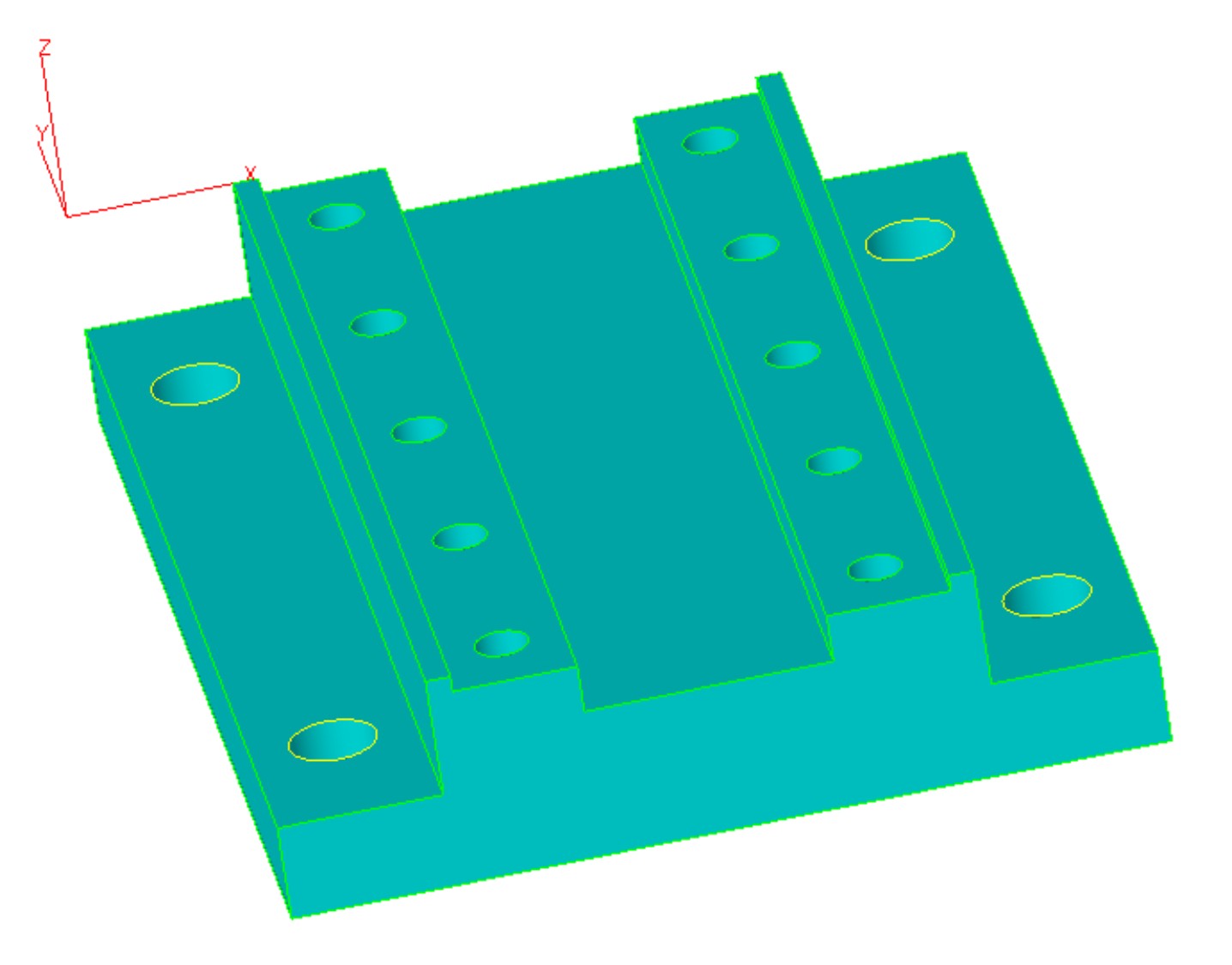
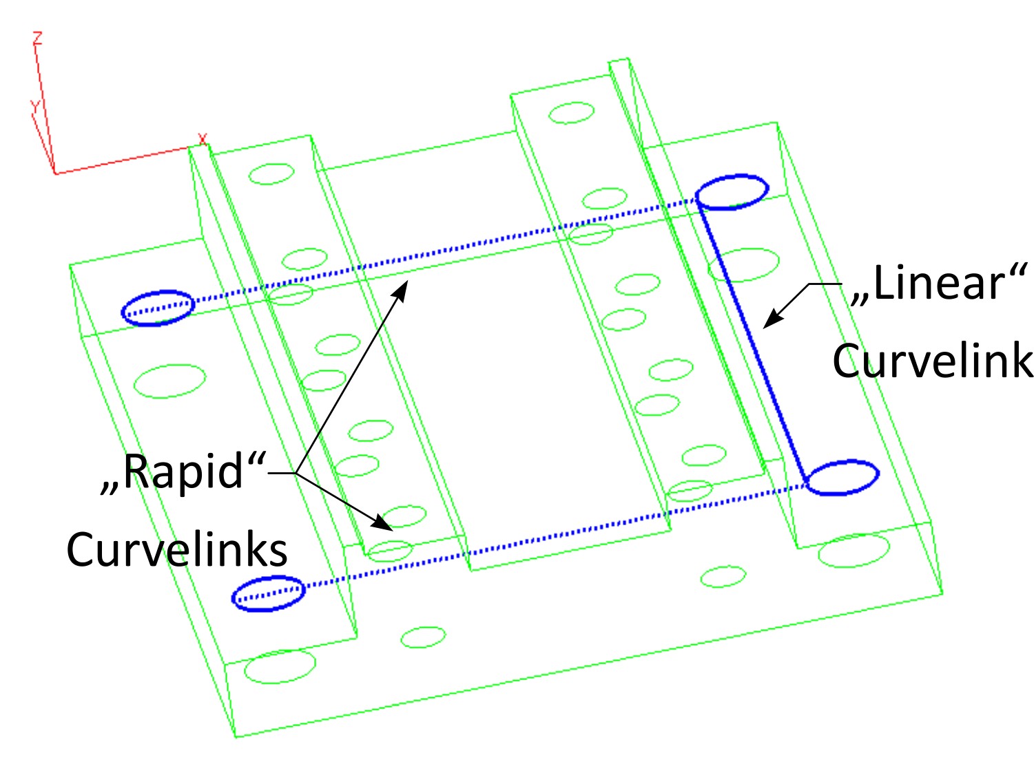
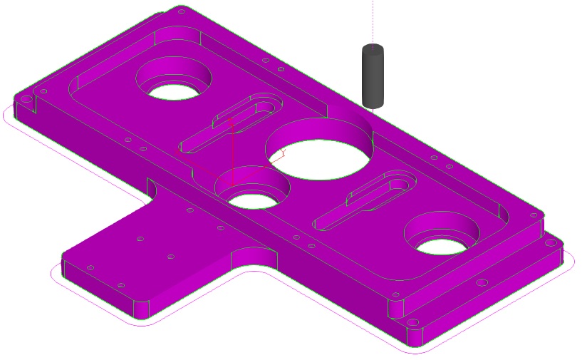
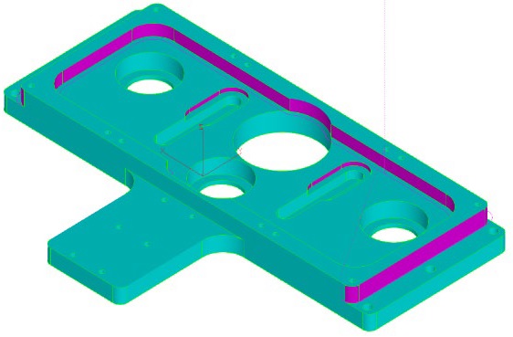
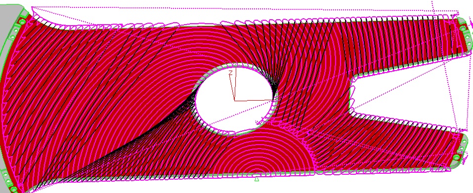
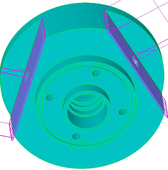
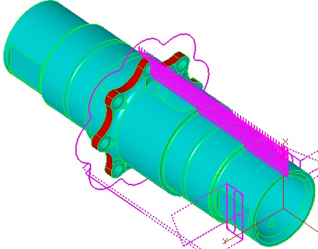
The four holes along the outside of this 3D model Resulting curve has two “rapid” links were
are to be manually chained into a new curve with collisions would occur
“RAPID MODE=OFF”
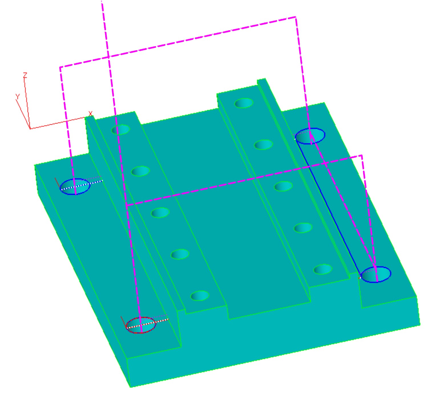
Toolpath retracts to “Z-RAPID” level along rapid “RAPID MODE” Toolbar Icon
curve links, while it stays down at “Z-CLEAR” level
along linear curve moves.
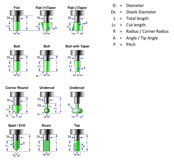
MILL / MILL-Pro – New Tool Properties “CUT LENGTH” & “SHANK DIAMETER”
To optimize visual toolpath check in 3D preview simulation additional new tool properties “Cut Length” and “Shank Diameter” have been added. These settings improve the tool display and allow better clash detection for standard and custom tools. Below we show the new settings in combination with the various tool types.
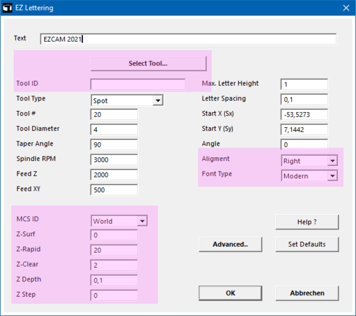
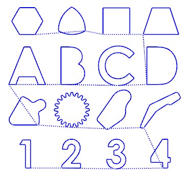
MILL / MILL-Pro / MILL Express – Updated Lettering Cycle
The “Lettering“ cycle has been updated and enhanced with some new options. The new “Select Tool“ button connects to EZCAM’s mill tool library for tool selection. Using the “Alignment” setting enables the user to align (Left, Right, Center) the text based on the defined X and Y start coordinates. The “Font” list offers two types of single-line fonts to create efficient NC-Code. Most noteworthy is the addition of the “Z-Data” settings, as this greatly reduces the need to continue to the “Advanced” machining dialog tab for further editing.
MILL / MILL-Pro – New “RETURN TO Z-CLEAR” Option
The new "Return at Z-Clear" option in Z-Data section allows 2.5D contouring, pocketing and zigzag toolpaths to rapid over at “Z-Clear” height when connecting consecutive Z level passes.
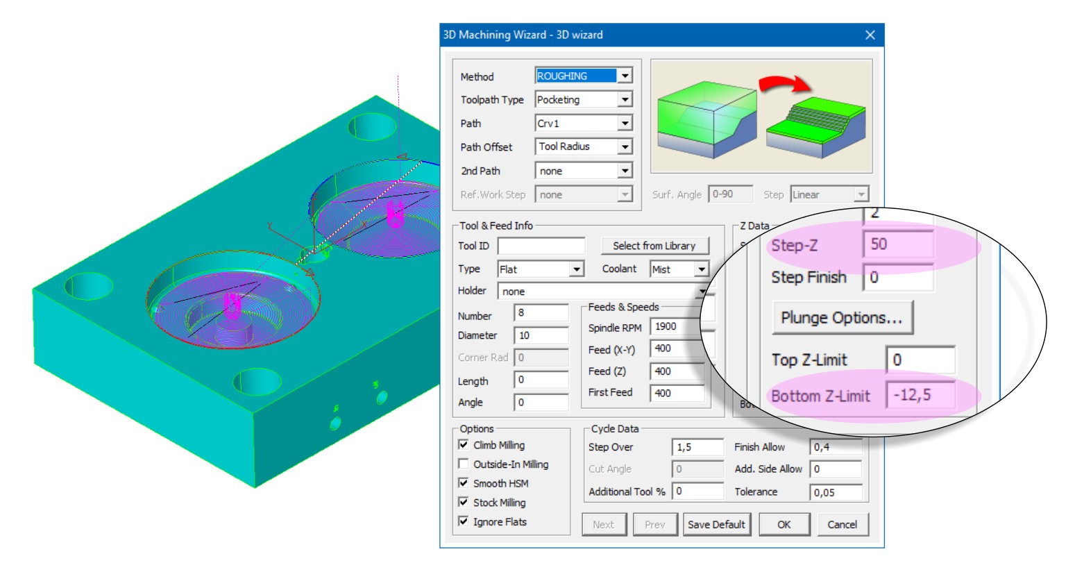
MILL-Pro – 3D Wizard – Single “KONSTANT-Z” Cuts possible
3D Wizard Constant-Z methods can now perform a single z-level cut defined by the lower z-limit if the z-step is set to a big enough value.
TURN – Updated “PECK STEP” Option now also for Contouring Cycle
The “Peck step" setting which has been introduced for “TURN” and “BORE” operations in the Cycle Data tab of EZCAM v2020 is now also available for “PROFILE” cycle operations. Clearance between two pecking steps is 0.1 mm and retract / engage moves are controlled by “Engage Angle”, “Clearance”, “Withdraw Angle” and “Withdraw Distance” parameters. In addition to this standard behavior, one can now use a negative “Peck Step”. This lets the system retract along the cutting axis only (usually Z) for chip breaking. Please note that in such cases, the verified toolpath cannot show any peck steps due to the cut and retract moves overlapping each other.
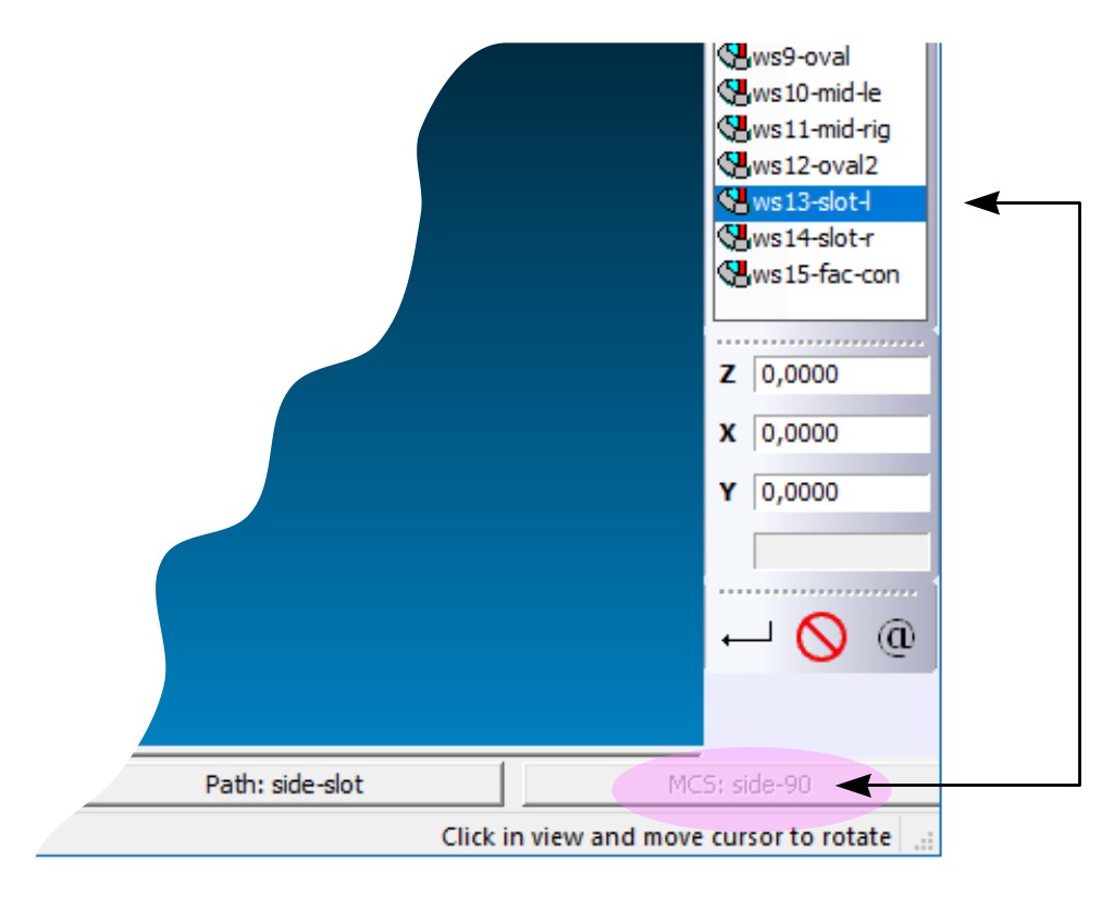
TURN – MCS System Display added to Status Bar
A new “MCS” button is added to the status bar of EZ-TURN so that sub-spindle and live-tool worksteps are more easily recognized by the selected UCS system.
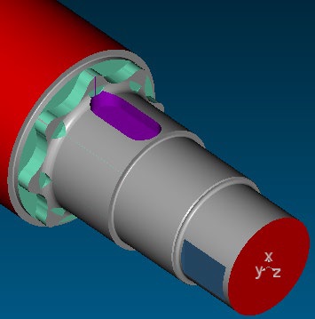
MILL / MILL-Pro / TURN / EDM – Updated “MACHINING SIDE – SOLID SURFACES” Command
The "Machining Side - Solid Surfaces" command has been much improved in speed and accuracy. This command should be applied when the user notices some faces of the closed body having the wrong side selected during CAD import.
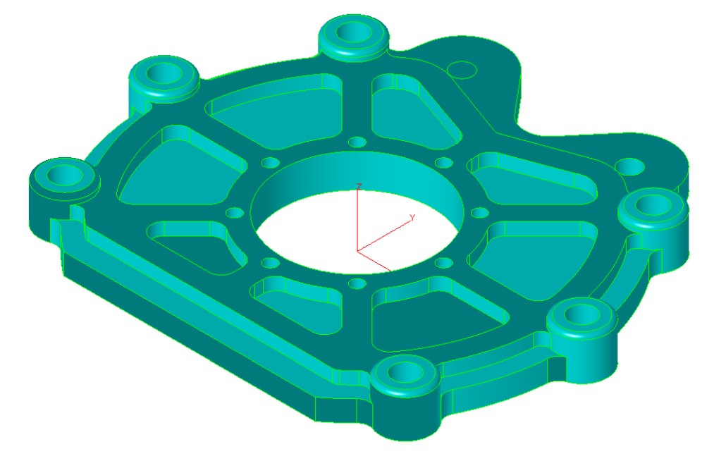
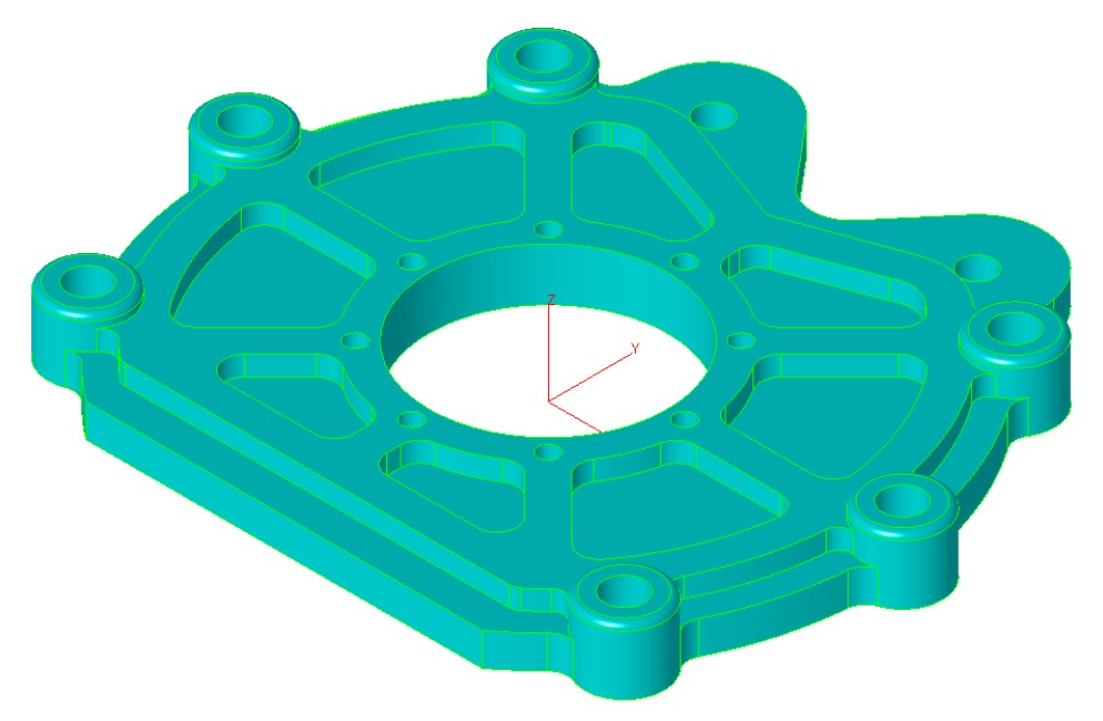
Imported CAD model with some surfaces having Corrected model after applying
their machining side set in wrong direction “Machining Side - Solid Surfaces” command
(darker coloured)
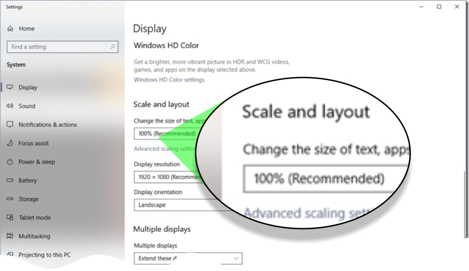
All Modules – Support of Windows Screen Scaling Option & “BASIC” Automation Update
While older windows versions, including first Windows 10 builds, provided options to directly set the font and size used in the application dialogs, the very latest Windows 10 builds offer only a global scaling factor which allows users to adapt the letter size to their screen size. This changed required us to modify EZCAM’s user interface with the help of a major update for our “WinBasic” automation language engine. While doing this many of the macro dialogs have been revised and improved by adding new functions and buttons, such as the new “Select Tool” command button in the MILL / MILL Express dialogs. The results have been successfully tested with scale factors of up to 200%.
October 2019:
Ez-Cam 2020 / V27 - Is here.
What’s new in EZCAM Version 2020 (V27)
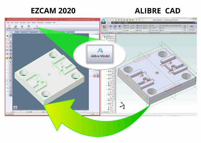
CAD Integration – Updated Data Transfer from ALIBRE CAD System
The “Update Alibre Model” command now transfers the exact model data rather than the current import/conversion process and updates previously loaded model quickly by only transferring modified faces preserving any world coordinate system changes. “3D-Wizard” Cut Surface tables are automatically modified after every Alibre model update and user-created face curves are renewed if its parent surface is modified. Alibre Design Setup is now part of EZCAM Setup so that all EZCAM users can easily see the benefits of our strong collaboration.
MILL / MILL-Pro / TURN / EDM – Copy & Paste Entities
The legacy commands “Copy from Rhino” and “Paste from Rhino”, found on the “Edit” menu, have been renamed as “Copy Geometry” and “Paste Geometry” respectively. These commands can now be used to copy & paste selected entities including surfaces into the current layer of the same or other EZCAM windows.
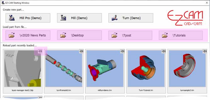
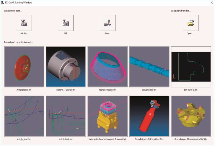
MILL / MILL Pro / TURN – Updated Startup Window
The enhanced Startup Window offers improved usability with new features. Up to four recently opened Part folders are included on top, above the recently loaded part images and both of them support tooltips displaying their full path names. “Right-click” on any recent part image in the EZ-CAM starting window shows that file in Explorer. User can pin/unpin any part file by clicking at the right top corner of its image.
Command button to “pin / unpin” a particular partfile to this location on dialog.
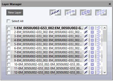
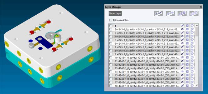
MILL / MILL Pro / TURN – New LAYER Manager
The new "Layer Manager", located in the “Edit” menu, opens a floating spreadsheet listing all layers used in the current partfile. The first column holds the “Selection Checkbox”, followed by “Layer ID” and “Blank”, “Delete”, “Copy” commands applicable to each specific layer (row). The “Layer ID” field can be slow clicked directly to “Rename” this particular layer’s ID. “Copy” command copies entire content of that layer into the new one. At the top of the dialogs window, the “Hide All”, “Show All”, “Delete All”, “Copy All” buttons are very helpful to work with multiple selected items. The current Layer, displayed on the “Layer ID” status button at bottom of the screen is displayed in bold letters.
“Layer Manager” toolbar shortcut
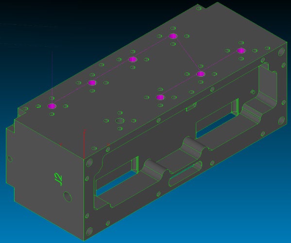
MILL / MILL Pro – Enhanced Hole Detection for 2D and 3D Data
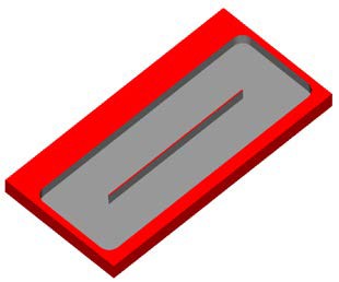
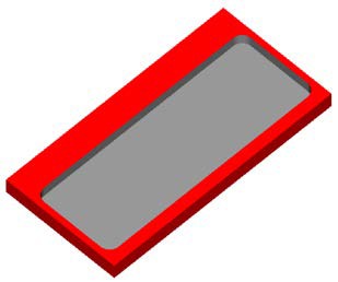
Several enhancements make it easier to work with holes in version 2020. All holes in the currently loaded model can be automatically closed by the new “Cap Holes” command located under the “Surface/Standard” menu. In addition, the “Hole Recognition” wizard now also detects circles in 2D drawings as drill paths and sets the associated “L” value (=depth) in the “Path ID” to “0”. Another enhancement now supports detection of Holes through surfaces if one of its ends is a flat circle.
Imported 3D Model Holes closed by “Cap Holes” command
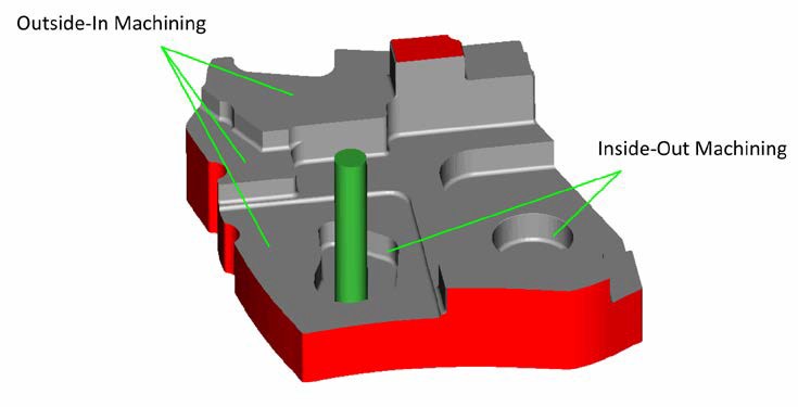
MILL Pro – 3D Wizard – Updated Constant-Z Roughing
3D-Wizard Constant-Z roughing method switches outside-in option automatically for each zlevel based on open/closed status of its loops.
MILL / MILL Pro – Surface Machining & 4th Axis Wrapping
4th axis wrapping is now supported by all projection machining cycles (Project=Facet) allowing one more finishing/roughing option for 3D-milling of surfaces. Remember though that tool will always be aligned to rotation axis centre.
MILL / MILL Pro – Standard Pocketing – New Variable Stepover Option
The new "Variable Step Over" option for non-HSM Pocketing operations applies adaptive stepover calculation to avoid unmachined areas. This new option is located on the “Cycle Data” tab of the machining dialogs.


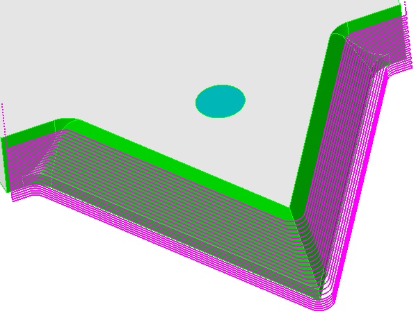
MILL / MILL Pro – Open-Edge Pocketing – New sharp Corner Handling
Open Edge pocketing has been completely redesigned to remove "roll around the edge" moves. Outside-in option for 3D roughing with stock milling option has been improved to make sure toolpath start-points are always located outside of the stock.
V2019 – Tool rolling around sharp edges V2020 – Tool cutting straight over sharp edges
MILL / MILL-Pro – New Lead-Out Move for Pocketing Operations
The “Finish Path” of Zig-Zag and Pocketing cycle operations now include lead-out moves for safe rapid-up without leaving a mark on the sidewalls.
MILL / MILL-Pro / TURN / EDM – Updated Solid Bodies CAD Import
When importing CAD files with multiple solid bodies EZCAM loads the entities of each body into a new layer created with the same name of the body. Using the new “Layer Manager”, each solid body can be blanked/un-blanked or even deleted by selecting the individual layers. Alternatively, all “Edit” menu group commands such as “Move”, “Translate”, “Delete”, etc. can use these layers as discrimination filters as well.
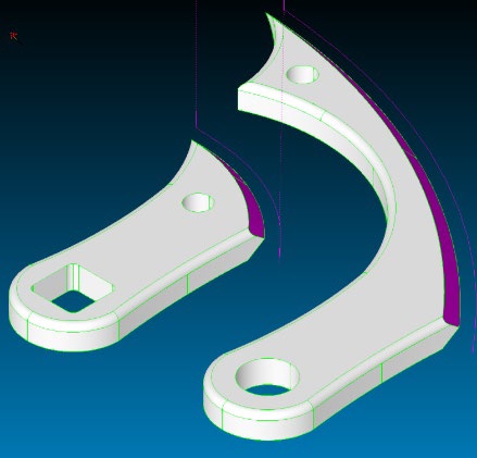
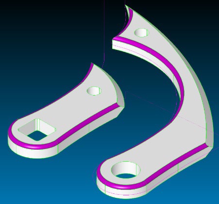
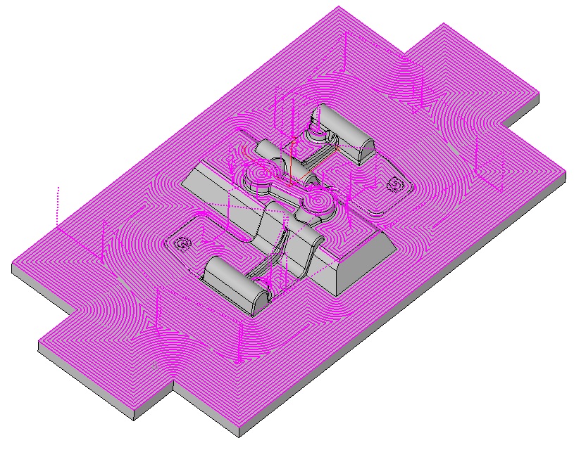
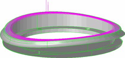
MILL Express – New Solid Model Support & Enhanced 2.5D Machining
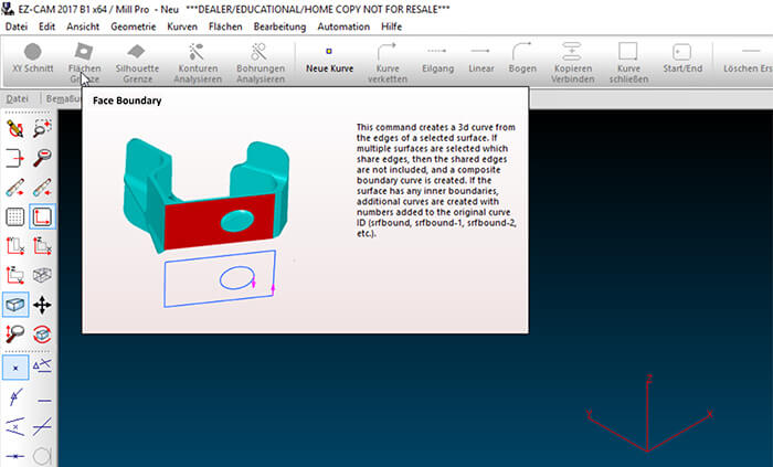
EZ-MILL Express product has been enhanced to support 2 1/2D milling of solid models and to offer starter level 3D machining. “Select Curves” (for machining) and “Face Boundary” with automatic open edge detection have been included in its “Machining” menu. 3D projection toolpaths can be created by utilizing the newly added “Select Cut” Surfaces. Copy Path command of Express won’t delete its existing path after appending the new one and all other path modify commands apply also to the curve selected by “Select Curves”.
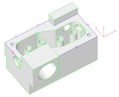
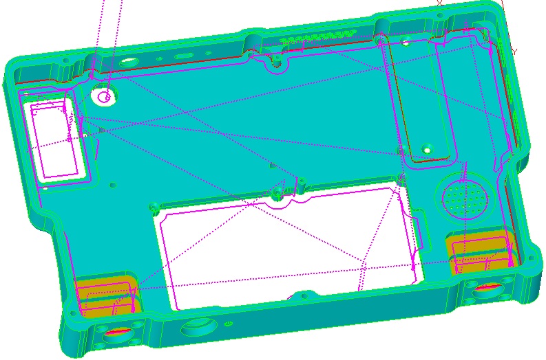
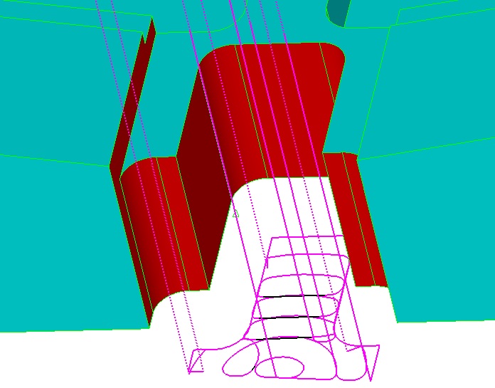
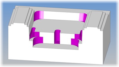
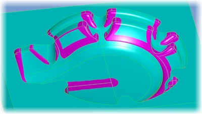
Imported 3D Model with Boundary Curves including open edges, marked by small magenta rectangles

Select Curve to be machined in current Workstep

Create Boundary Curve from Surface with Open-Edge Detection
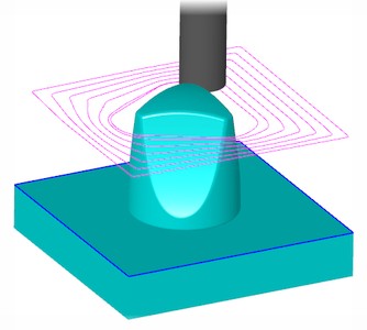
Select Surfaces for Toolpath to be projected onto
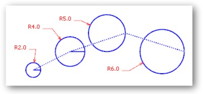
MILL / MILL-Pro / TURN / EDM – New Radius vs. Diameter Toggle
Radius entry can be toggled to Diameter entry by clicking on letter R and vice versa making it easier to input diameter values shown in the drawings.
MILL / MILL-Pro / TURN / EDM – Enhanced SNAP ALL Command
The “Snap All” - Point Picking option now also snaps at middle point of line/arc entity and centre point of circle entity, allowing geometry creation with far less mouse clicks.
MILL / MILL-Pro / TURN – Enhanced POST Dialog
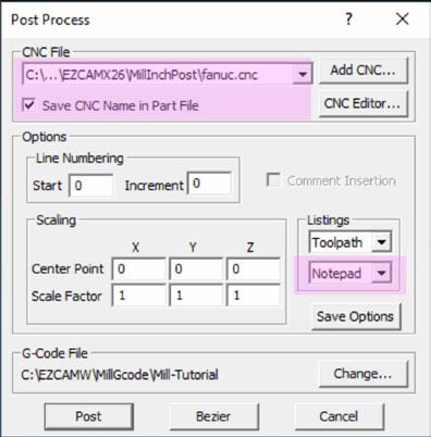
The EZ-CAM “Post” dialog is one of our main focuses in version 2020. A new listbox has been added to the “Listings” section, providing three options “None”, “EZ-DNC” and “Notepad” to be used as G-code editor. Also, recently used CNC files (post processors) are listed to save cumbersome browsing during each postprocessor change. Finally, the "Save CNC Name in Part File" option saves and reloads the last postprocessor used from the current part file.
MILL / MILL-Pro / TURN – New Utilities Toolbox
A new “Toolbox” sub-menu with some good utility functions has been added to the “Help” menu. Especially the new item to activate/deactivate worksteps with several options proves to be very helpful.
MILL / MILL-Pro / TURN – Spreadsheet Updatedx
EZCAM’s famous Spreadsheet required major internal modifications to make it compatible with recent operating system updates. The new release now also displays the row of the current workstep in red (if inactive light red) for easier recognition and access. In addition, the “First Feed” parameter, important to control variable feedrate adaption for HSM pocketing operations (0=variable feedrate), has been added as a new column.
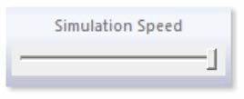
MILL / MILL-Pro / TURN – Simulation Speed Slider on Toolbar
A new Simulation speed slider bar can be placed on any of the command manager tabs for quick access.
MILL / MILL-Pro / TURN – New AUTO Update Function
"About EZ-CAM" window in the help menu of version 2020 includes the new "Update" button for patch installation which does not require uninstall and preserves all default parameter settings and layout info. Also, it is good to know EZ-CAM version 2020 network keys can be ordered for any # of licenses.
All Modules – AutoCad 2019 and Solidworks 2019 Support
The CAD import filter for STEP data has been modified and updated extensively. In addition, the Solidworks import has been upgraded to support latest 2019 file types.
TURN – Stock Curve creation TUBE Option
The stock curve creation dialog has been updated to support “Tube” type of workpiece.
October 2018:
Ez-Cam 2019 / V26 - Is here.
What’s new in EZCAM Version 2019 (V26)
MILL / MILL Pro / TURN – New Startup window
The small dialog for selection of the current EZ-CAM module that came up in previous versions when the File/New command was selected has been replaced by a splash-screen dialog having many more options. When starting EZ-CAM or selecting the File/New command, the new dialog enables selection of the most recent part files for both MILL and TURN modes. In addition, when the desired file is not among these, one may alternatively click the “Open...” button to browse and find the file and open it. Either way the system will automatically start in the correct mode according to the selected file type. And, as with the old dialog, clicking any of the “MILL-PRO”, “MILL” or “TURN” buttons will start the system with an empty document in the mode selected.
MILL / MILL Pro / TURN – Improved Drag & Drop Functionality
In addition to the new splash screen mentioned above, drag & drop files onto the EZ-CAM icon or the application window (an overlooked but very handy feature), has been reworked as well.
• Dropping any file onto the desktop icon opens the application in the correct mode depending on the file type (MILL or TURN).
• When dropping a file onto an existing EZ-CAM window, the file will be loaded on top of the already existing data. If the file type is different to the existing session, as for example dropping a “TURN” file onto a “MILL” session, an automatic restart in the new mode is done before loading the data.
• Any EZ-CAM supported CAD file (DXF, IGES, STEP, etc.) dropped onto the application window will automatically be imported.
MILL / MILL Pro / TURN – New Web Tools for remote editing of Worksteps
When starting up new parts, users very often modify CAM generated NC code directly on the machine, due to part, tool, or machine-specific reasons. To keep the associated CAM file current, the machinist typically needs to note any changes and manually update the associated CAM file. Then, only after re-posting, will the code for this part include the changes.
Now, with EZ-CAM “Web-Tools”, we introduce a new method to revolutionise this process by enabling the user to remotely edit workstep-related parameters. With Web-Tools, part data (workstep parameter & snapshot image) can be uploaded to our new web service, EZ-CAM Online. The data can then be accessed via any web browser, running on any operating system (Android, iOS, Windows) on hardware such as tablets, smart phones, or laptops. Any modifications done via the remote devices can later be downloaded to EZ-CAM through Web-Tools to update the original part file on the PC.
• Access to EZ-CAM Online service for registered users.
• EZ-CAM Online is supported in any browser on mobile devices using Android, iOS, or Microsoft Mobile operating systems.
• Only workstep related machining information is shared, no sensitive part data (dimensions, geometry, surfaces, toolpaths, etc.) is uploaded.
MILL / MILL Pro / TURN – New "Floating Spreadsheet"
EZ-CAM’s unique Spreadsheet control – displaying the most important workstep related machining data for easier editing – can now be opened as a floating window to be moved around on the same machine’s screen or even on an external monitor. Such dual-monitor users will greatly benefit from keeping the separate spreadsheet window constantly open, allowing direct editing on one side while viewing the part and verifying the toolpath on the other.
Monitor #1 displaying EZ-CAM‘s main “Floating Spreadsheet” as separate
application window window on second Monitor
MILL / MILL Pro / TURN – Double-Click on Spreadsheet to open Full Machining Dialog
Although many key machining settings are directly accessible via the spreadsheet, sometimes users need to modify other settings and accordingly will open the full machining dialog. In previous versions this was not possible from inside the spreadsheet. Now in release 2019, the full machining dialog can be opened by a simple double-click in the first column of the spreadsheet in the row of the workstep to be edited.
MILL / MILL Pro – Updated World on Model command, loads “Stock Model”
A new "Load Stock" option was added to the World on Model command, originally introduced in version 2018. This option loads any 3D file format with surfaces to be merged into one closed surface named “stockSrf”, representing the stock model with transparent color (white). In addition, the “Stock Type” on the “Stock Setup” dialog is automatically set to “Custom stock”.
MILL / MILL Pro – Zig-Zag Cycle – Finishing Path with Ramps Moves
The Finishing Pass of the Zig-Zag cycle, intended to clean the ridges along the machined profile, now includes automatic lead-in moves to avoid over-stressing the tool when entering the remaining material. The lead-in length is automatically set to 50% of the defined Step Over distance.
MILL / MILL Pro – 3D-Wizard – Constant-Z Finishing with Flat Regions
A new update to the 3D-Wizard’s Constant-Z Finishing method always includes passes for “flat regions”.
MILL / MILL Pro / TURN – Enhanced Toolpath Display Performance
The display performance of very large toolpaths has been updated and greatly improved.
TURN – Roughing Cycles – New “Peck Step” option
EZ-TURN introduces the new “Peck Step” parameter for Turn, Bore and Face roughing cycles. Clearance distance between two pecking steps is 0.1 mm, and retract and engage moves are controlled by “Engage Angle”, “Clearance”, “Withdraw Angle” and “Withdraw Distance” parameters.
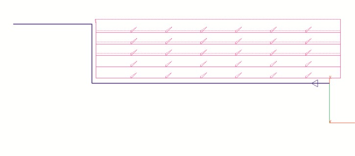
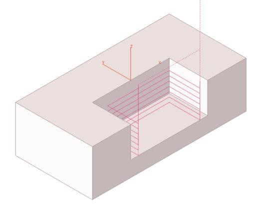
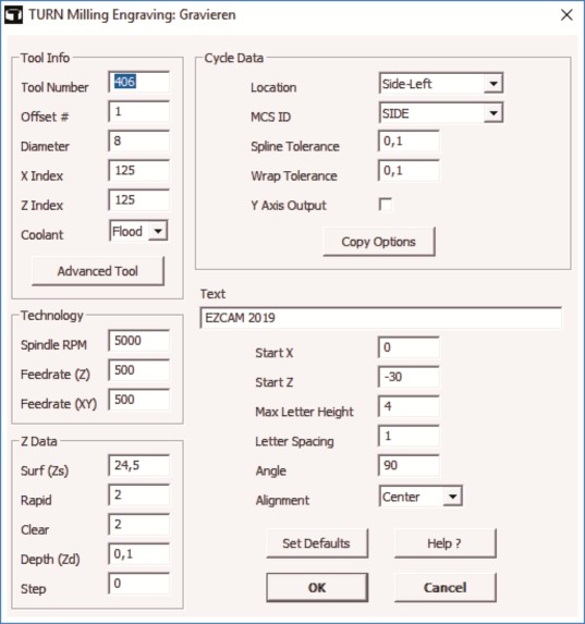
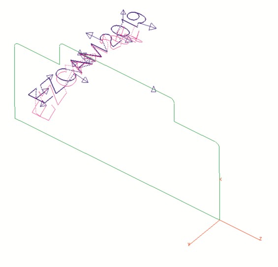
TURN – New “Engraving” Cycle
Improving on previous releases, the new “Engraving” cycle lets you define the technology data, as well as the engraving specific parameters, all in one dialog. The path curve is created automatically, and toolpath can be verified right away, anytime. Modifying the text only requires opening the workstep, changing the text, closing the dialog and then re-verifying or posting the toolpath.
TURN – Enhanced Cutoff Cycle
The Cutoff cycle has received a major upgrade with the addition of some very frequently requested features:
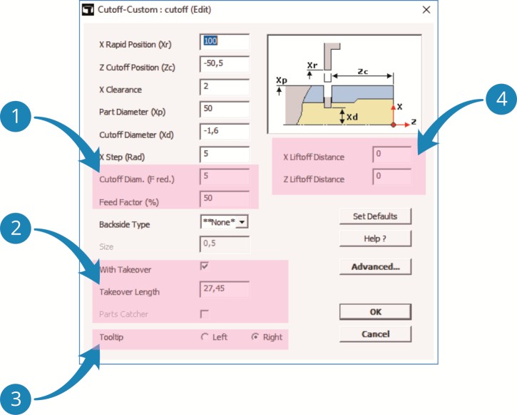
The new settings “Cutoff Diameter (F-reduced)” and “Feed Factor” allow performing the final stage of the cutoff process using a reduced feedrate.
As an alternative to the (newly updated) Parts Catcher option, the user can also define a “Takeover Length” that is passed to the NC code that handles part-takeover on Sub-Spindle machines.
Regular EZ-CAM cycles always explicitly use the left edge of a cutoff tool – the new “Tooltip” option of the “Cutoff” cycle, however, allow you to select which edge of the tool, left or right, is measured and defined by the corresponding offset on the machine. For this the cycle will use the workstep’s “Tool Width” setting to correctly calculate toolpath and NC code, respectively.
“X Liftoff Distance” = X retract distance when doing multiple X steps during the cutoff.
“Z Liftoff Distance” = Z retract distance after cutoff move.
EDM – Verification now with “Real Wire Offset”
The Contouring, XYUV and Die/Punch cycles now verify the wirepath using different offset values for multiple passes. If the technology table provides valid offset values (between 0 and twice the wire diameter), the system will use these, otherwise it will compute a standard value between the wire radius and wire diameter for each pass. In the case of multiple passes, the interval will be divided equally among those.
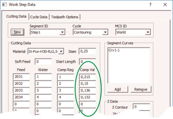
The “Comp-Val” section where the offset for each pass is defined.
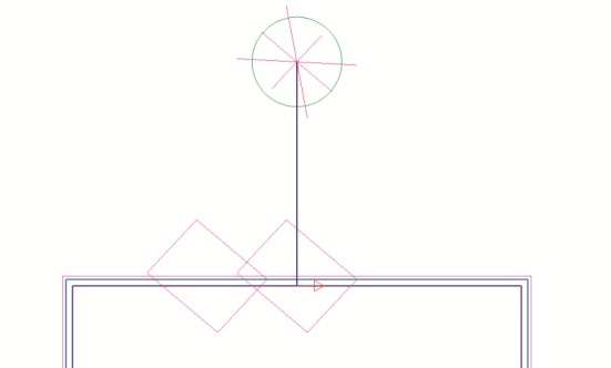
Verified toolpath with multiple passes (offsets).
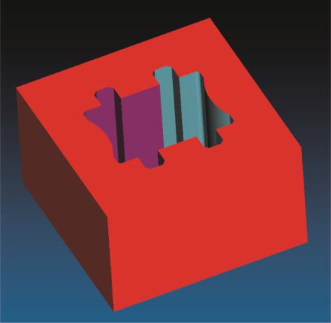
EDM – Enhanced Wirepath 3D Simulation
The updated 3D simulation now uses different colors for each pass along a certain profile and hides the bodies split away from the stock automatically. In addition, the background color of the simulation window has been changed to a gradient display.
EDM – Pocketing Cycle – New “Radial” Option
In release 2018, the Pocketing cycle’s wirepath was converted to the more efficient trochoidal style. In the 2019 release the new “Radial” setting gives the option to switch between old-style parallel pocketing (Radial=Off) and the new trochoidal style (Radial=On). In addition, the trochoidal style has seen several improvements in respect to reduced cut/thread occurrences and better wire/part collision checks while moving inside the pocket at rapid feedrates.
Radial 'Off' Radial 'On'
MILL / MILL Pro / TURN – Post Processor ID and G-Code File Extension stored in Part Files
The name of the last used post processor (machine specific NC code configuration file) is now directly saved into the part file together with the file extension used for the G-Code file. This information is then restored automatically when the partfile is opened again.
MILL / MILL Pro / TURN – Updated Worksheet Document
Create Worksheet Document now includes the image of the part at the top of the page.
All Modules – Enhanced STEP and AutoCAD 2018 DWG Import
The CAD import filters for STEP data has been modified and updated extensively. In addition, the AutoCAD DWG import has been upgraded to support latest 2018 file types.
All Modules – CAD Import – Automatic Geometry Cleanup
Overlapping lines/arcs are deleted during CAD import so that chain command can now be used on the solid wireframe geometry as an alternative method for rapid curve creation.
All Modules – Gradient 3D Simulation Background
Gradient is now the standard background color for the simulation window of all EZCAM modules.
November 2017:
Ez-Cam 2018 / V25 - Is here.
What’s new in EZCAM Version 2018 (V25)
MILL / TURN / EDM – New Toolbar Colour Scheme and Menubar with Icons:
The new toolbar colour scheme and the new menu bar with icons left of menu items add clarity and consistency making EZ-CAM 2018 look great. Command Manager can be optionally docked to bottom using the new setting in the Customise dialog and function keys can be assigned to the command buttons of the currently selected tab.
MILL / TURN / EDM – Drag-and-Drop Items From Menus to Toolbars:
In EZ-CAM 2018 more customisation options have been introduced. Drag-and-drop items from menus to toolbars is now possible. Menu items can also be dragged within the same menu or into other menus. Pop-up menus can be created via right click. All of these can be now achieved when in customisation mode.
MILL Pro – 3D Wizard – Unlimited Number of Re-Roughing:
Unlimited number of reroughing operations can be created for the same 3D roughing workstep. Each reroughing worksteps references the previous reroughing workstep in the chain.
MILL / MILL Pro – 4th Axis Wrapping - Finishing Rotational 3D Models:
4th axis wrapping function for finishing rotational models can now be performed using contouring cycle with multiple link path curve and machining surfaces. 3D step-over can be specified with curve step parameter or helical option can be activated for continuous rotation.
MILL Pro – Largest Flat Diameter and Largest Corner Radius Commands:
Largest Flat Diameter and Largest Corner Radius commands offer great help in selecting the correct tool size. Both commands apply multi-core processing for better performance.
Largest Flat Diameter command finds the largest flat Largest Corner Radius command analyses the complete
tool size that machines the part with the least rest model and provides the largest tool radius possible
material possible and reports the corresponding rest and reports the corresponding rest material percentage.
material percentage.
MILL Pro – Uncut Model Percentage:
Uncut Model % shows percentage of total surface area reachable from +Z by the currently selected workstep’s tool. This command also creates uncutSrf to display inaccessible regions.
Uncut Model % command marks the inaccessible regions Uncut Model % command marks the inaccessible regions
for the selected tool on a part with planar surfaces. for the selected tool on a part with a complex shape.
MILL Pro – 3D Wizard – 3D Roughing Helical Outside-In Pocketing:
Helical outside-in pocketing is now possible in 3d roughing method. This strategy will now skip the first pass if 3d roughing or if 2d face milling is active.
MILL / MILL Pro – Thread-Milling 4th Axis Index-Repeat Parameters:
Index-repeat parameters are supported by threadmilling.
MILL / MILL Pro – Hole Recognition - Max Limit For Circle Radius:
Hole recognition's max limit for circle radius can be customized using [ML3D] maxHoleRadius setting in "ezcam.ini" file.
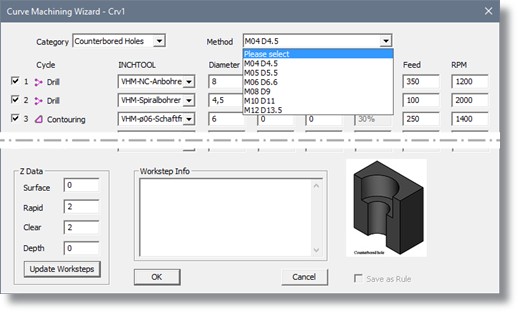
MILL / MILL Pro – Hole Detection Function Counter Bore Support:
Hole detection command now recognizes cylindrical counter bores (metric M4, M5, M6, M8, M10, M12) which can be then machined using pre-defined methods of Curve Machining Wizard. Furthermore, performance of hole detection has been much improved.
MILL Pro – Refinishing Toolpath - Constant-Z Section Enhancement:
Constant-Z section of refinishing toolpath will now support open surface link type correctly.
MILL / TURN / EDM – Chain Type Setting and Auto Chain Function Covers All Figures:
Circle Chain option is renamed as Chain Type and can be used for any shape.
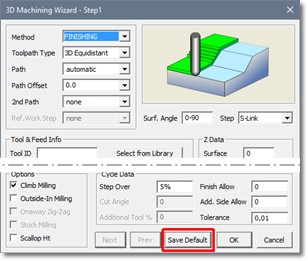
MILL Pro – 3D Wizard - Save Default Button:
Save Default button has been added to 3D-Wizard dialog.
MILL / TURN / EDM – Imported DXF/DWG Spline Profiles - Optimized Arcs:
Spline profiles in DXF/DWG files will be imported as optimized arcs.
TURN Express / TURN – Bi-Directional Multi-Pass Profile Cycle Support:
EZ-Turn multi-pass profile cycle now supports bi-directional option of cycle-data dialog.
TURN Express / TURN – "Create Worksheet Document" Feature:
Create Worksheet Document has been added to the Help menu of EZ-TURN Express.
EDM – Pocketing Cycle Trochoidal Strategy:
EZ-EDM pocketing cycle utilizes trochoidal strategy for burning out small cavities.
EDM – XYUV Cycle Multiple Shape Support:
XYUV cycle supports machining multiple shapes within one workstep. Path curves need to be selected in the following order: crv1Lower, crv1Upper, crv2Lower, crv2Upper, etc.
MILL / TURN / EDM – Solidworks 2018 Sldprt Files Can Now Be Imported

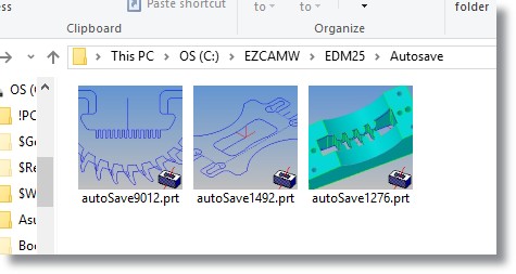
EDM – Autosave Using Different Filename For Each Session:
Autosave function will save part files in the sub-folder named Autosave using different filename for each EZ-EDM session.
EDM – Max. Hole Radius Setting for Skipping Automatic Lead In/Out:
[EDM] maxHoleRadius setting in "ezcam.ini" file allows Chain circles command to skip automatic lead in/out from the centre point.
MILL / TURN / EDM – Enhanced Overall Graphics Display Performance
Overall graphics display features are fine tuned and the performance is enhanced in EZ-CAM 2018.

EDM – Select Entities First Option:
Select Entities First option has been added to EZ-EDM.
EDM – Copy/Paste Worksteps Between Different Sessions:
Copy/Paste worksteps between different sessions is now also available in EZ-EDM.
October 2016:
Ez-Cam 2017 / V24 - Is here.
What’s new in EZCAM Version 2017 (V24)
MILL / MILL Pro / TURN – Thumbnail Icons with Preview Image:
The EZCAM v2017 setup automatically installs a new DLL that allows the Windows operating system to display thumbnail icons with preview images inside its native file explorer. In addition, the preview image is now stored inside EZCAM’s own EZ-MILL (*.3DP) and EZ-TURN (*.TRN) part files. In comparison to earlier EZCAM versions, which stored the preview images as separate files, the new method ensures preview availability even when files are copied over non-windows networks and systems.
MILL / MILL Pro / TURN – Revised Tooltips for Command Buttons:
To further improve usability, the tooltips for command buttons now include videos, graphics and multiline text. Especially new or non-regular users will benefit from this fast and more comprehensive help. At the same time, these tooltips have a little delay time build in, so that workflow for experienced users will not be affected.
MILL Pro – 3D Wizard – New “Stock Milling” Roughing Option:
The new “Stock Milling” option found on the “3D Wizard” dialog now gives users two options of how to handle any selected check surfaces. If unchecked, check surfaces define the area that should be avoided by the toolpath. If checked, check surfaces represent the stock model which has to be removed.
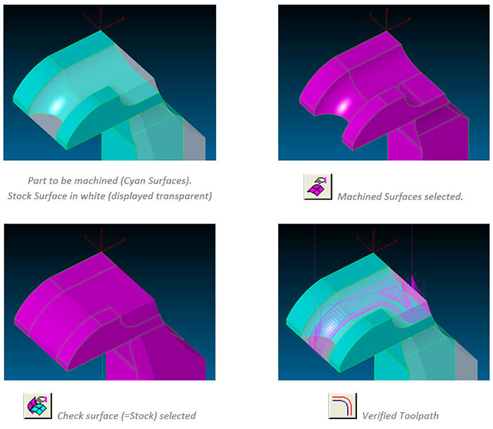
MILL Pro – 3D Wizard – Refinishing Method combines Constant-Z and Equidistant Toolpath:
Refinishing operations now automatically combine “Equidistant” and “Constant-Z” toolpath types. By using the “Surface Angle” setting, the user defines the angular limit that is machined using the “Equidistant” method. For example, by setting surface angle to “0-50” degrees, all areas up to 50° are refinished using the “Equidistant” method while the rest, up to 90° is machined using the “Constant-Z” method. Please note, that the lower value of the “Surface Angle” setting is always ignored and regarded as being “0”.
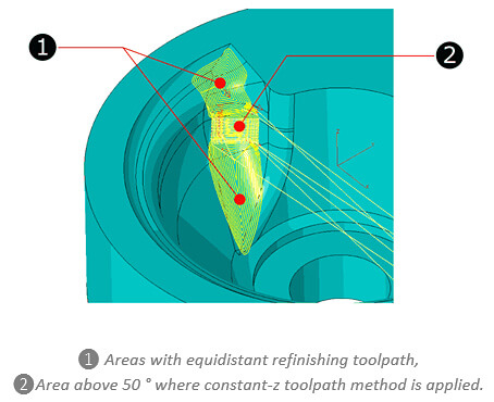
MILL Pro – 3D Wizard – Finishing support for Draft Angle Tools:
The 3D-Wizard’s “Equidistant” and “Constant-Z” finishing methods now support the use of tools with draft angle defined by the tool angle setting.
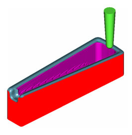
MILL Pro – 3D Wizard – New “Outside-in” Roughing Option:
If the “Outside-in” option is checked, any “3D-Wizard” roughing operation tries to detect open edges along the selected surfaces. If any detected, the toolpath for every Z level pass starts at a plunge location using “Step-Over” distance away from the open edge
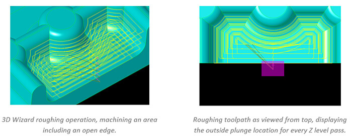
MILL Pro – 3D Wizard – New “Additional Side Allowance” Finishing Option:
A new “Additional Side Allowance” setting is now available for “3D-Wizard” roughing and finishing (Constant-Z and Equidistant) operations. This enables users to give the system a separate XY finish allowance, regardless of any surface “Finish Allowance“.
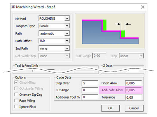
MILL Pro – 3D Wizard – Revised “Outside-In” Equidistant Finishing Option:
The task of finishing flat areas of a 3D model has been optimized. When “Equidistant” finishing is used in combination with the “Outside-In” option and a “Surface Angle” set to “0” (= only flat areas), the toolpath automatically starts at any open edge that is detected.
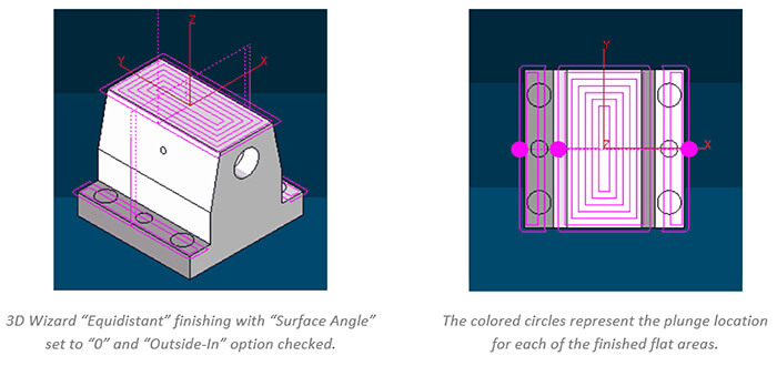
MILL Pro – 3D Wizard – Worksteps as Templates:
By using the new “Save Defaults” button on the 3D wizard dialog, all current settings can be saved as templates for future use. When creating a new wizard workstep, the workstep ID dialog provides a list box, offering all available wizard templates for selection.
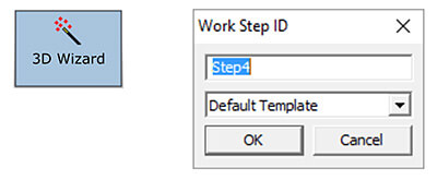
MILL Pro – 3D Wizard – “Constant-Z” Finishing with new “Maximum Z-Step” Option:
When using the “Variable Step” option for “Constant-Z” finishing operations, the applied Z-Step per pass is calculated by the system, based on the specified “Scallop Height” for the resulting surface. Sometimes, especially along completely vertical surface areas, this resulted in step sizes that exceeded the tools machining capabilities. To avoid this, the new “Max. Step” settings now allows to set a maximum step value to avoid this.
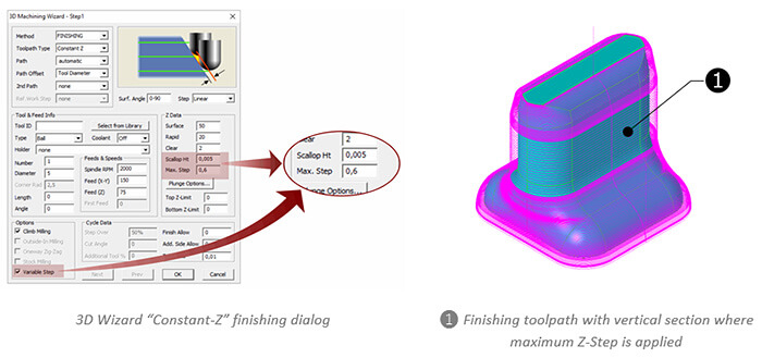
MILL / MILL Pro / TURN – Revised Postscript (EPS) Data Import:
When importing data in EPS (Encapsulated PostScript) format, curved profiles were often converted into tiny linear moves, increasing file size and making machining more difficult. In addition, this also had negative effects on the profiles visual quality. To improve this, EPS data imported via the “File Open” command is now automatically optimized into tangent arcs and line entities where ever possible. The graphic below represents the reduced number of curve entities in an imported and optimized EPS file.
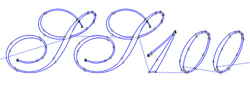
MILL / MILL Pro / TURN / EDM – Revised CAD Data Import:
When importing CAD data (STEP, Parasolid, Solidworks, etc.), a three step process is started. First, all surface data is converted into corresponding EZCAM entities. Second, boundary geometry is created for all surfaces. In addition, the system checks boundary quality of adjacent surfaces to prevent double geometry creation. In the third and final step, the system tries to detect arcs or lines that represent full circles and converts them into circle entities. Now each of these steps roughly uses one third of the total import time. To improve performance, the last two steps (geometry creation and circle detection) can be disabled. Both can be executed later by using the new “Surface Edge Geometry” command, found in the “Geometry” menu. Another benefit is the reduced amount of data to be hold in memory after import. This greatly improves general handling performance and makes it for example easier to extract the part to be machined from a complete CAD assembly.
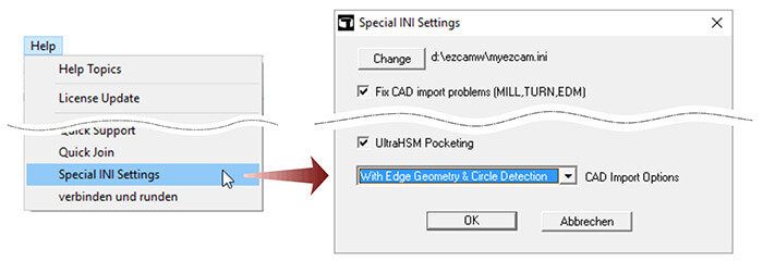
MILL / MILL Pro / TURN – New “Select Entities First” Option:
Some commands (Translate, Move, Rotate, Mirror, Scale) found in the “Edit” menu require a special sequence to be followed. Depending on the command you need to select points or insert values such as translation distances or scale factors. Once this is done, the affected entities are selected. The new toggle “Select Entities First” optionally reverses this process. You can first select the entities, then handle the remaining data as required. Many users may find this sequence easier to follow and should therefore be able to increase their productivity.
MILL / MILL Pro / TURN – Updated Solidworks Import (64-Bit only):
The EZCAM core and related import libraries have been updated to allow Solidworks 2016 SLDPRT files import. However, this functionality is only available for 64-Bit EZCAM modules.
MILL / MILL Pro / TURN – Updated “Chain” Curve Command:
Due to various requests, the curve “Chain” command has been updated. Beside the fact that the number of entities to be chained is now unlimited, this command saw several improvements regarding visual feedback during the chaining process. Especially when chaining multiple profiles, the system now gives continuous feedback by highlighting already chained blocks on the screen. In addition, a progress bar is displayed at the bottom of the screen, indicating that the process is still ongoing.
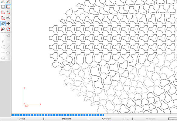
MILL / MILL Pro / TURN – Open Post Editor Modules:
The “Post Process” dialog received a new button to directly load the current postprocessor into the corresponding postprocessor editor, MBuild for MILL and TBuild for TURN.
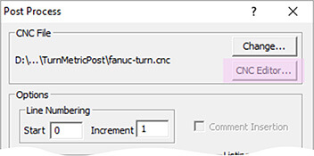
TURN – Target Part Creation by Curve:
When using the “Stock and Optimization Setup – Create Uncut Solids” option to compare the as-cut verification model to the original CAD model, a so called “Target Part” representing the final 3D model of the part needs to be defined. Usually this is done by a single STL surface named “targetsrf“. New in TURN v2017 is the option to define the target part in form of a simple 2D curve named “targetCrv“. This curve represents a cross sectional profile that is automatically converted to a target part model by 360° rotation around World Z axis.
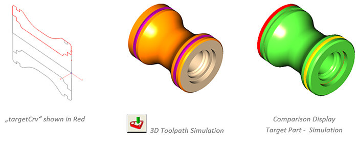
TURN – Updated Live-Tool Dialog with default Feed and Speed:
The “Advanced Tool Options” dialog, used in all live-tool cycles, has been updated to support the default settings for feedrate and speed, retrieved from the current live-tool tool database.
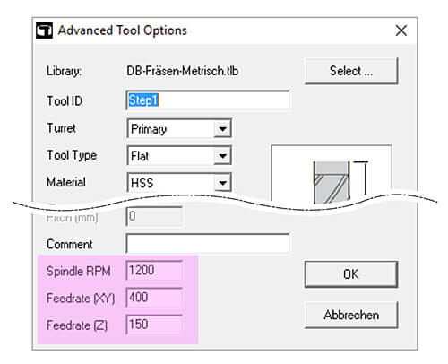
TURN – Updated Turn Tool Library:
The standard tool library that is shipped with all EZ-TURN modules has been extended with many new tools and tool holders.
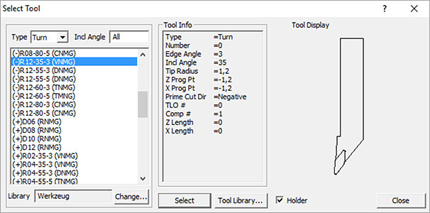
EDM – Updated Auto Start/End Automation Command:
The new “Punch Special” option was added to the “Autostart for all Curves” function dialog, found in the “Automation” menu. Originally this command only added “Lead In/Out” moves along the outside (Punch) or inside (Die) of all visible curves, including any appended sub profiles. The new “Punch Special” feature now always places the start point of the next profile in-side the previous profiles (already cut and removed) loop.
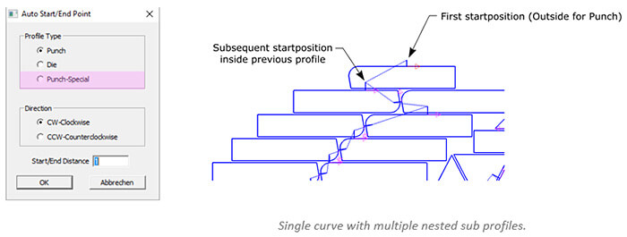
EDM – DIE Machining – Updated Technology Data Calculation:
The use of technology data files in combination with the DIE wizard has been revised to fully support correct assignment of cutting data to the various DIE sections (Conic1, Land, Conic2).
Depending on the selected “DIE” and “Sequence” type, the corresponding cutting height is calculated and displayed on the “Set Technology Data” dialog. According to the displayed height, the “Calculate” button now retrieves the correct conditions for each section.

EDM – XYUV Machining – Additional Return Distance for Multiple Passes:
The “Return Distance” setting found on the “Cycle Data” dialog is now also available for XYUV machining operations. At the end of the second pass, the wire usually moves back all the way to the original start point of the curve. When applying more than 2 passes, this behavior is unnecessary and time consuming. Therefore, if “Return Distance” is set, the system retracts only by this value, before continuing with the third pass.
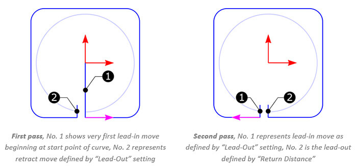
October 2015:
Ez-Cam 2016 / V23 - Is here.
What’s new in EZCAM Version 2016 (V23)
MILL Pro – 64-bit Edition is Ready:
EZ-MILL Pro 2016 comes with a 64-bit edition which now makes it possible to import and create 3D toolpaths for very large and complicated solid models.
MILL Pro – Fine Tessellation of 3D Models:
Fine Tessellation option introduces a new triangulation module creating gap-free models which take up less memory but are well within chordal tolerance. Models imported with this option allow higher quality 3D toolpath creation.
MILL / MILL Pro – Curve Feature Recognition:
New Curve menu command "Pocket, Face, Contour Recognition" detects pockets in the currently selected UCS as curves named as "P" and colored red, faces named as "F" and colored blue, contours named as "C" and colored yellow. All paths not 100% accessible and circular paths smaller than 1 inch (12mm) diameter are omitted.
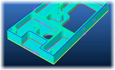
MILL Express – ultraHSM (smooth HSM) Feature:
EZ-MILL Express includes ultraHSM high-speed pocketing as standard feature. Constant material removal rate is obtained by feedrate optimization and circular cutting passes in combination with radial ramp in/out moves guarantee a continuous toolpath without any sharp corners. This reduces machining time and increases tool life by up to 10 times.
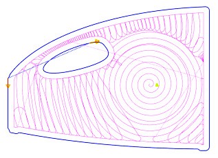
MILL Express / MILL / MILL-Pro – Corner Rounding for Multiple-Pass Contouring:
If cut step parameter of Contouring cycle is defined to create multiple passes and smooth HSM option is enabled system rounds sharp corners in all passes except the last one.
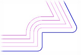
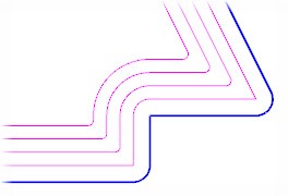
Multi-pass contouring | smooth HSM option: Disabled Multi-pass contouring | smooth HSM option: Enabled
MILL / MILL-Pro – Face Curve Detects Open Edges:
Face curve command includes a new option to automatically detect open edges.
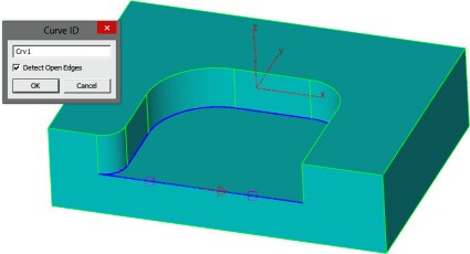
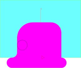
"Detect Open Edges" option marks open edges Top view of the simulation result for pocketing
of the newly created curve operation using this curve
MILL Express / MILL / MILL-Pro – Open Edge Pocketing Fine Tuned:
Open edge pocketing can now handle most complicated cases.
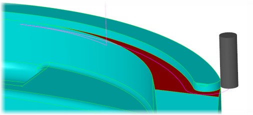
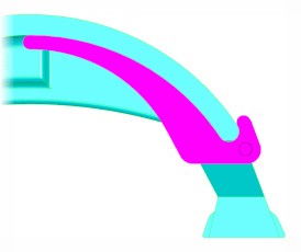
Red surface has open edges along narrow stripes Top view of the simulation result for pocketing operation
using the face curve of the red surface
MILL Express / MILL / MILL-Pro – Adaptive Z-Step for Top/Bottom Fillets:
For top and bottom fillet options of draft data, Z-Step parameter becomes stepping distance along the arc.
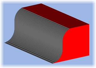
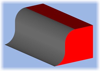
Top and bottom fillets machined by constant Z-steps Top and bottom fillets machined by adaptive Z-steps
MILL / MILL Pro / EDM – Compute Volume & Area Command:
Compute Volume command now calculates also the area enclosed by the current curve.
MILL Express / MILL / MILL-Pro / TURN Express / Turn – Autosave with Session Number:
Autosave files are saved in "Autosave" folder in ezcam23 and session number is appended to their filenames.
MILL Express / MILL / MILL-Pro – Draft Angle | Z-Step Connect Option: When draft parameters are applied, Connect option in Z-Data can now be activated to eliminate all rapid travels.
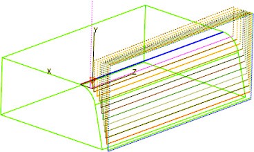
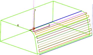
Z-Step | Connect Option = Disabled Z-Step | Connect Option = Enabled
MILL Pro – 3d Toolpath Calculation Performance Enhancement:
Calculation performance for 3d wizard methods are optimized by compressing tessellated triangle data of the 3d solid model.
MILL Pro – Small Features to be Suppressed in Roughing:
3D Roughing method offers a new parameter to set an additional tool diameter percentage which can be used to avoid the tool entering into regions which are smaller than the tool diameter plus the additional percentage. This option is essential if the tool can not plunge into the material directly and the figure does not offer enough space for alternative plunging options such as helical or zigzag.
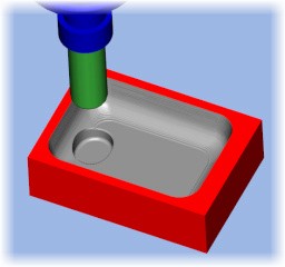
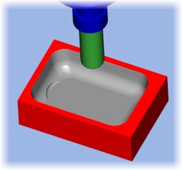
Workpiece containing a small pocket at the bottom Features smaller than the "tool + additional tool diameter"
are omitted in 3D Roughing
MILL Pro – 3D Equidistant | Fine Surface Finish:
3D equidistant method with ball end tool supports now EZCAM's proprietary "Top" projection method to get very fine surface finish. This innovative method refines the toolpath by increasing the accuracy of its points using the analytical definition of the 3d model.
Simulation result of the industry standard facet Superb surface finish quality achieved by 3D Equidistant
calculated surface finishing toolpath using EZCAM's proprietary "Top" projection method
MILL Pro – Roughing from Stock | Path Offset Setting:
Roughing from Stock method utilizes path offset setting to extend the toolpath outside.
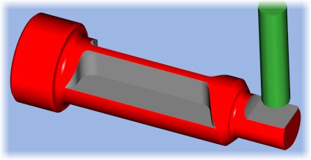
Roughing applied from a cylindrical stock with
the setting "Path Offset = Tool Diameter"
MILL Pro – Constant-Z Roughing | Plunge Point Enhancement:
Outside-In option selects adequate start points in constant-z roughing levels.
MILL Pro – Re-Roughing | Minimize Jumps:
If min jumps is turned on in re-roughing method toolpath passes are ordered by region minimizing rapid travels.
MILL Express / MILL / MILL-Pro / TURN Express / Turn – 3D Preview Simulation | Different Color for each Tool:
Preview simulation command uses different color for the material cut by each tool.
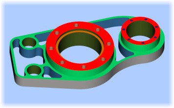
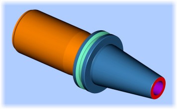
EZ-MILL | Different simulation colors for each tool EZ-TURN | Different simulation colors for each tool
MILL Express / MILL / MILL-Pro / TURN Express / Turn – 3D Simulation | New Stepping Options:
Simulation Setup dialog includes a new setting to select simulation stepping type as SINGLE, Z-RAPID UP, WORKSTEP or TOOL CHANGE. When system stops you can hit enter key to step or left mouse click to continue.
EDM – XYUV Profile Matching for XY Intersection Curves:
XYUV profile matching using geometry lines is extended to support curves created by XY-Intersection.
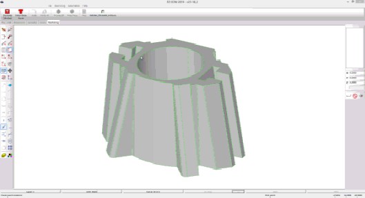
EDM – "Auto Create XYUV" Workstep command:
Automation Command "Auto Create XYUV" creates complete workstep just in seconds after user picks only the upper and lower z-levels from the solid model. Thanks to the above-mentioned "profile matching by XY intersection curves" feature, upper and lower profiles are automatically matched.
MILL Express / MILL / MILL-Pro / TURN Express / Turn – New Toolbar Group | Advanced Viewing Buttons:
New floating toolbar with advanced viewing buttons (such as back, right front bottom, left and all other common viewing angles) can easily be activated via space bar shortcut key.
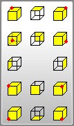
MILL / MILL-Pro / Turn / EDM – Check Angle Command Supports Surfaces:
Check Angle command can now be used to display the angle between two surfaces.
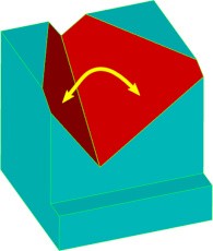
MILL Express / MILL / MILL-Pro – Simulate Tool | Dynamic Viewing Commands:
Simulate Tool feature supports dynamic viewing actions (such as dynamic rotation, zooming, panning) during simulation.
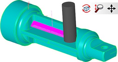
EDM – 3D Simulation Creates Machined Part as Solid Body:
“Create Part Solid” option in “EZ-EDM | Stock Setup” lets 3D Preview command create solid bodies named “PartSrf1, PartSrf2, etc.”.
October 2014:
Ez-Cam 2015 / V22 - Is here.
What’s new in EZCAM Version 2015 (V22)
MILL / TURN / EZCAM Express – Updated Spreadsheet Module:
After many years of excellent service, EZCAM’s unique spreadsheet module has been replaced and functionally enhanced to answer various user requests and operating system requirements. Below you’ll find the list of its most important new features.
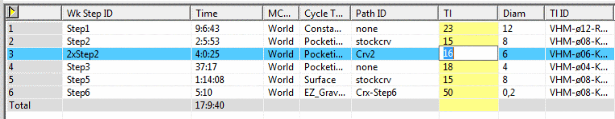
• The content display is improved by use of different colors to highlight current row, column and selected field.
• Columns can be reordered by drag and drop.
• You can hide/show columns in “customize” mode, activated by either pressing “Alt” key or displaying the “Customize buttons” dialog from the “View” menu. Columns to be hidden are then displayed in purple and removed from the table upon exiting customize mode.
MILL / TURN – New single Workstep Templates:
The “Save Defaults” command, located in the tabbed machining dialogs, can now be used to save the settings of the current workstep as template for subsequent operations. User is prompted for a template ID to save current settings in a “3dp” (Mill) or “trn” (Turn) file under that name in predefined subfolders, “WorkstepTemplateMetric” or “WorkstepTemplateInch”. If the “ID” input field is left as “Default”, then current settings are saved into the “ezcam.ini” file to be used as “Default Template”. When creating a new workstep, the ID input dialog now also displays the template list which includes “Default Template” as the current selection followed by the names of any available templates. If no templates exist this list is not included.
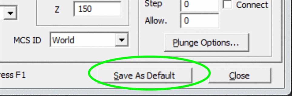
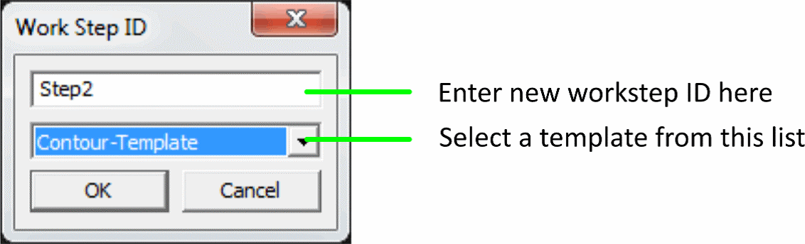
„Save Default“ button on workstep dialogs Dialog when creating a new workstep
MILL-Pro – 3D Roughing using UltraHSM toolpath:
3D Roughing operations using the “Pocketing” toolpath type now also support the “UltraHSM” option, previously only available for 2.5D pocketing. Constant material removal rate is obtained by feedrate optimization and circular cutting passes in combination with radial ramp in/out moves guarantee a continuous toolpath without any sharp corners. This usually reduces machining time and increases tool life by up to 10 times.
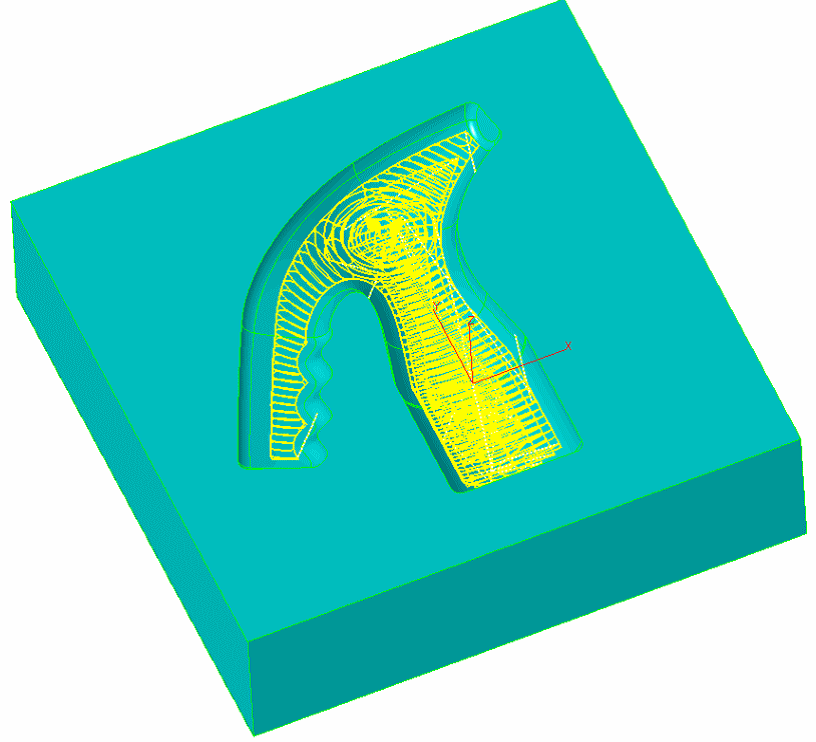
MILL-Pro – 3D Wizard Roughing – Z step smoothing:
Pocketing and Zig-Zag types of Roughing methods of the 3DWizard can now automatically create refinishing Z step passes between two consecutive roughing levels to reduce the resulting steps along the part wall. If “Step Finish” parameter in “Z-Data” section is defined, then these methods use “Step-Z” to calculate the roughing levels each of which is followed by refinishing passes calculated using “Step Finish” parameter. As a result, the remaining steps along the part surface are much smaller, leaving less material to be removed by subsequent finishing operations.
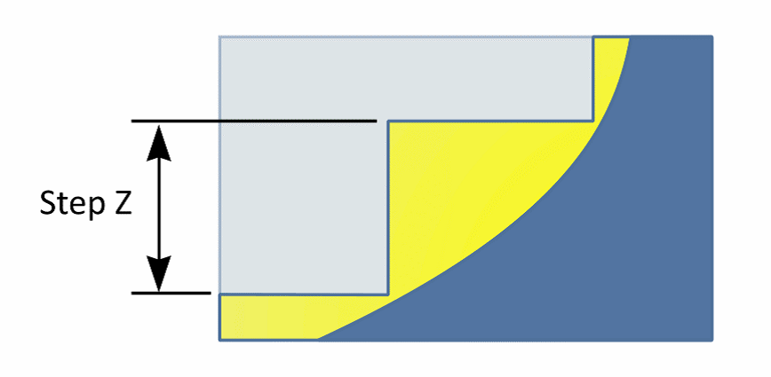
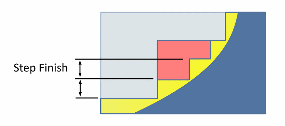
Regular Steps without Z refinishing Red area removed by Z refinishing
MILL / MILL-Pro – Pocketing with continuous Stepover:
The 2,5D Pocketing cycle now includes the new “Helical” option (see “Cycle Data” tab) to create a helical continuous toolpath, completely avoiding any direct plunge into the material. Below you can see two examples of basic pocket profiles demonstrating nicely the new helical toolpath strategy.
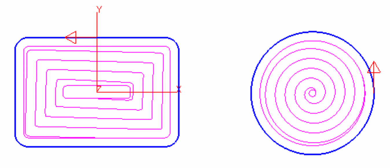
MILL-Pro – Constant-Z & Equidistant helical step method:
The 3D wizards “Equidistant” and “Constant-Z” finishing methods also provide the new “Helical” step type to create a continuous toolpath which improves surface quality by avoiding marks created by direct step-over moves between finishing passes.
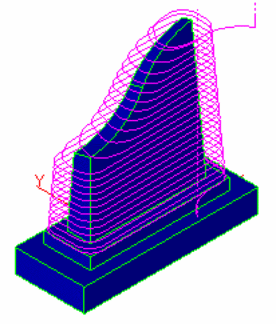
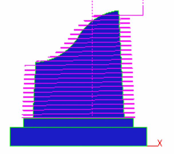
“Constant-Z” finishing using “Helical” step method
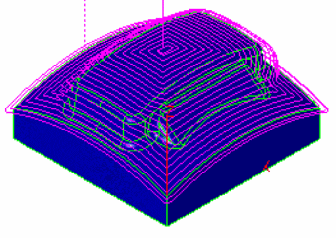
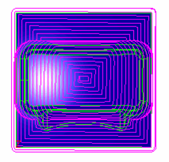
“Equidistant” finishing using “Helical” step method
MILL-Pro – Constant-Z Finishing – Checksurface Support:
The 3D wizards “Constant-Z” finishing method now supports check surfaces which can be selected to define a machining boundary. The toolpath will then automatically start at the open edge if selected cut surfaces are not closed. In addition, with “Step” type set to “Linear”, one can use the “Plunge Options” to apply any combination of linear or arc ramp moves. The machining direction can be controlled via the “Climb Milling” option.
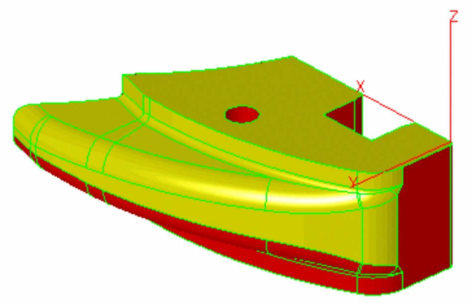
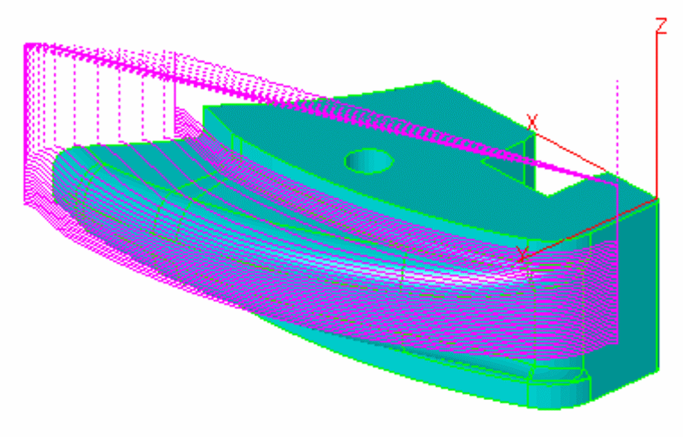
Yellow = Selected Machining Surfaces “Constant-Z” Toolpath
Red = Selected Check Surfaces
MILL-Pro – Constant-Z Finishing – Connected Toolpath:
For 3D wizards “Constant-Z” finishing worksteps, the “Connect” option, located in the “Z-Data” section of the “Tool Info” machining dialog, can be used to create a bidirectional toolpath eliminating rapid-over moves.
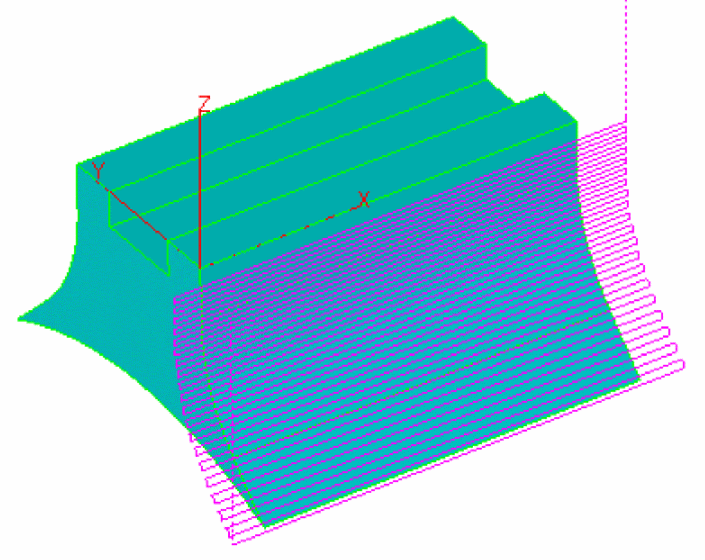
“Connected” Toolpath
Note:
The “Connect” option can only be used in combination with “Step” type set to “Open Surface” in the wizard dialog. If any kind of ramp moves (see “Plunge Options”) are also applied or the machining direction is changed ( see “Climb Milling”), it may be necessary to adjust the “Offset Dir” setting located in the “Cycle Data” machining dialog.
MILL-Pro – Constant-Z & Equidistant revised surface angle limits:
The 3D wizards “Equidistant” and “Constant-Z” finishing option to limit the toolpath by defining surface angle has been completely revised. It now apply limits correctly onto the toolpath itself rather than the surface model as in prior versions.
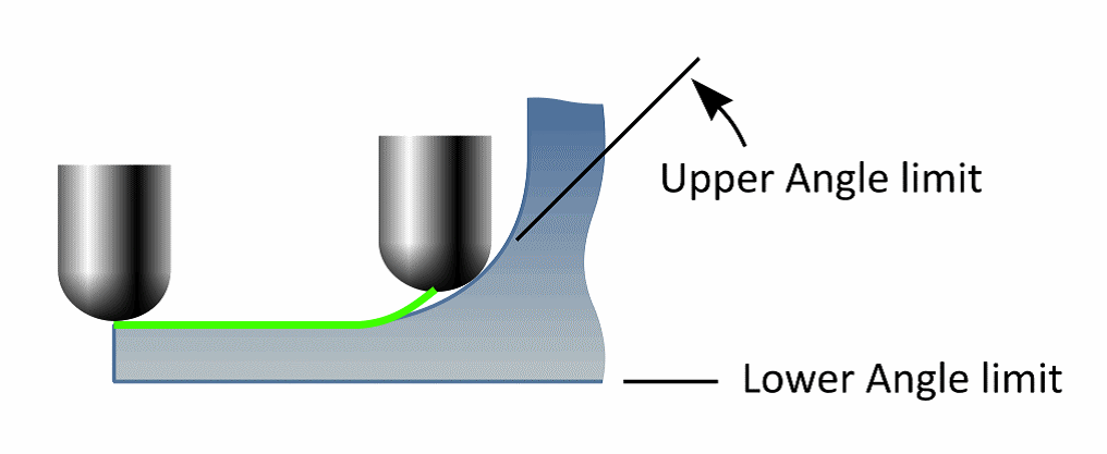
MILL-Pro – Re-Roughing Open-Edges Support:
The 3D wizards “Re-Roughing” method is enhanced to correctly support regions at the open edges of the model.
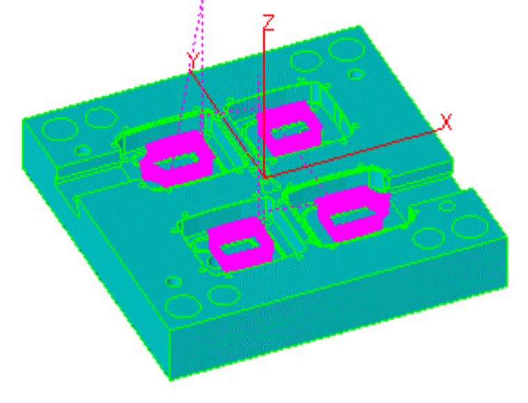
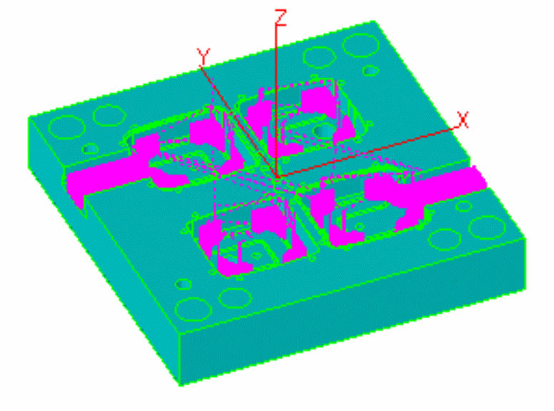
”Roughing” Operation ”Re-Roughing” Operation
MILL / MILL-Pro – “Outside-In” roughing & Toolpath Startpoint:
When applying the “Outside-In” option (see “Cycle Data”) to 2D “UltraHSM” pocketing operations, the toolpath now starts at the closest location to the start point of the path (selected curve).
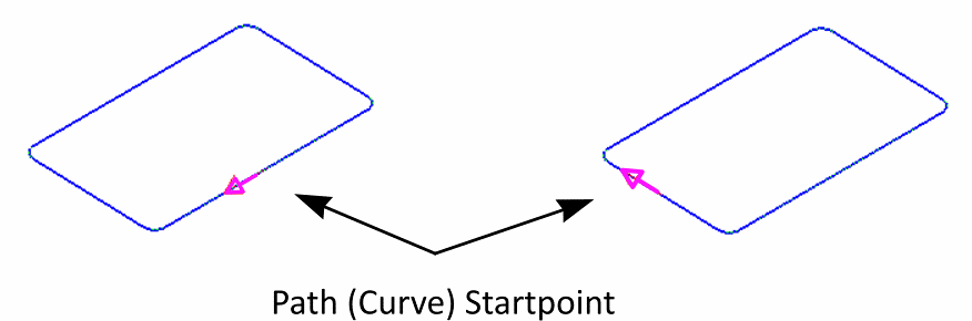
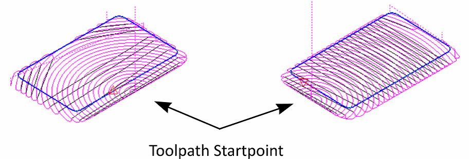
MILL / MILL-Pro – Curve Wizard new “Save as Rule” function:
The curve wizard now displays the new "Save as Rule" setting to associate the current curve name with the currently selected machining feature. A rule is established by matching certain section in the curve ID with the selected wizard method. For curves representing holes, this identifier section starts with the letter “D” followed by the hole diameter (format "XXXXD###.###XXXX"). For general shapes any text preceded by the “-“ character (format "XXX-yourtext”) can be defined as the identifier. Curve wizard searches the identifiers of all pre-defined rules in the ID of the current curve and if one detected the method defined by that rule is preselected.
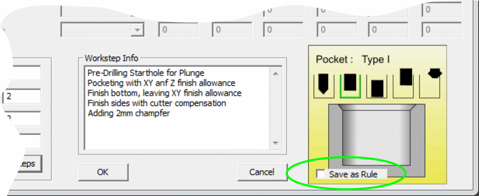
Example:
The current curve is representing some holes of diameter 5.2mm. The name of this curve was manually defined as “Crv5-D5.2-backside”. You then open the curve wizard, select “Holes” category and “Hole-D5.2” from the “Method” list. Before closing the wizard, the “Save as rule” option is activated. EZCAM now associates the string “D5.2” with the method “Hole-D5.2” and saves this information in its INI file. Next time you open the wizard with a curve having “D5.2” in its ID, the “Hole-D5.2” method is automatically preselected. This is especially helpful when using the “Hole Recognition” command (see “Curve” menu) which automatically creates drilling curves with ID’s containing their diameter value preceded by the “D” character.
MILL Express / MILL / MILL-Pro – Updated “Auto” Depth command:
The “Auto” command button for “Z-Depth” setting (see “Tool Info” dialog) now copies the value from the “Z-Coordinate” entry box if there is no path curve selected or if the selected path is at Z-Surf level.
MILL / TURN / EZCAM Express – Show Toolpath with new “Auto Update“ option:
The “Show Toolpath” list found in the “Setup” dialog (see “View” menu) now includes the new “Auto Update” option. This lets the system automatically redraw any 2,5D toolpath whenever a related workstep setting is changed. This removes the need to call “Verify” for toolpath recalculation after every parameter change.
MILL / TURN – Updated Stock Setup:
The “Stock Setup” dialog (see “Machining” menu) includes a new list to redefine the “World” origin at the selected location of the box representing the stock limits. When opening the dialog its default setting is “Current Part Origin” followed by the new options “Top Middle”, “Front-Left”, “Back-Left”, “Front-Right” and “Back-Right”. When one of them is selected, the “WORLD” coordinate System is moved to that location instantly.
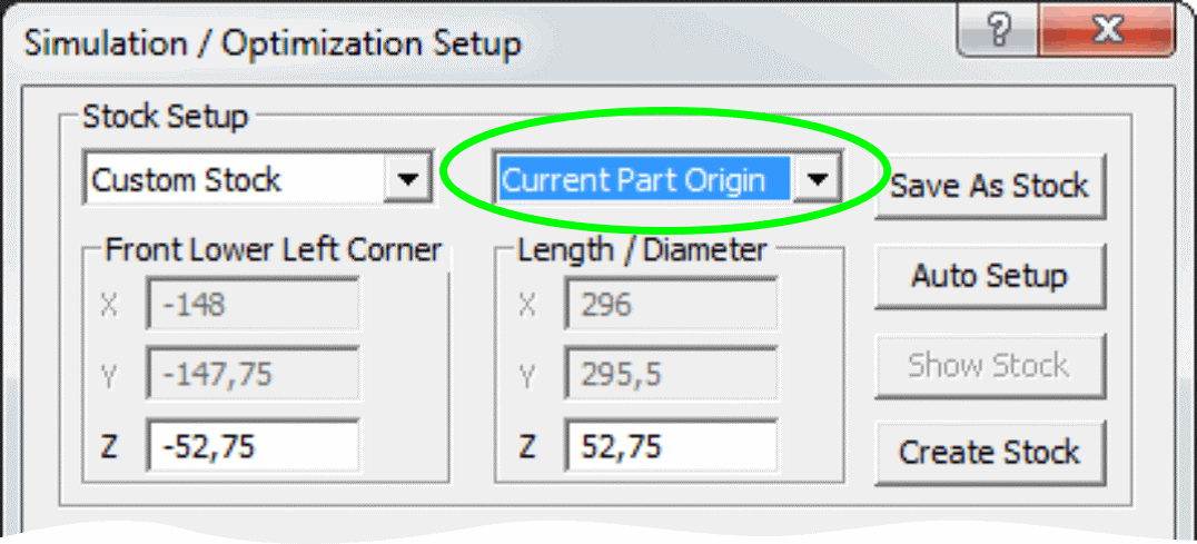
MILL / TURN / EDM – Location of “EZCAM.INI” file:
The “ezcam.ini” initialization file is used to save various settings such as workstep default values, last used filenames, postprocessor, etc. Depending on the current UAC (user account control) setting this file is located directly in the windows main folder, or in a specific user subfolder. EZCAM version 2015 now offers different methods to customize the location of ezcam.ini. Its pathname, for example “c:\windows\ezcam.ini”, can now be a command line argument in the EZCAM program shortcut allowing working with different copies of ezcam.ini. The “Special INI Settings” dialog under “Help” menu has been updated to allow customization of this pathname as well. It can also be changed by directly setting a value for the registry key: HKEY_CURRENT_USER\Software\EZ-CAM\General\Settings\IniFilename.
MILL Express / MILL / MILL-Pro – Updated Threadmilling Cycle:
The „Threadmilling“ cycle has been updated with several new features. First, it now supports the selection of multiple machining curves by using the „Select Curves“ command (see „Machining“ menu). In addition it is now possible to define any angle between 0 and 359 degrees in 1° steps as the toolpath’s „Start Angle“. Another enhancement is the automatic 180° ramp-in/out move for cases where tool diameter and “Root Diameter” do not leave enough space for regular ramp moves. The pitch applied to these 180° ramp moves is 0,15 x regular pitch.
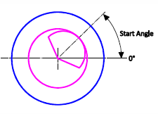
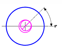
New „Start Angle“ option180° Ramp-In/Out moves
MILL Express / MILL / MILL-Pro – Updated Lettering Feature:
The “Lettering” cycle provides a quick solution to engrave text input by using the simple “Modern” font. Beside some internal modifications a new “Angle” field has been implemented. This allows rotation of the text around the coordinates defined by the “Start X” and “Start Y” settings.
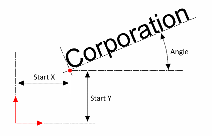
MILL Express – Updated Machining Dialogs:
The simplified user dialogs found in Mill Express have been updated to reflect latest changes in the software. The “Contour” cycles dialog now controls the “Offset Dir.”, “Cutter Comp” and “Lead In/Out” settings and activates/deactivates certain fields based on current selections. Instead of using fixed values for ramp moves it now sets a percentage of the tool diameter as the ramp radius and linear lead length settings. In case cutter compensation on the control is used, this percentage is 60%, for all other cases 10%. This way, it is not necessary any more to change these settings whenever“Tool Diameter” is changed. The “Pocket” and “Face” feature dialogs now also support percentage character input for the “Stepover” setting.
EDM – Updated PUNCH & DIE Wizards:
The “Punch” and “DIE” wizards have been added some new strategies, which allow greater flexibility when machining sets of multiple parts with different material, thickness or surface finish. The earlier existing strategies always combined “Main”, “Finish” and “Cut-Off” operations in a single workstep. Using this approach it was impossible to use the wizard for multiple parts requiring different number of passes or different conic settings. With the newly added strategies, these cut methods are now available as separate items. For example, you can now define multiple “Punch3” (Main & Finish) worksteps, each with different settings for material, number of passes, or workpiece height. These can be then followed by multiple “Punch4” worksteps to cut them off. Similar changes have been applied to the “DIE” wizard, which now also has separate strategies for “Main”, “Finish” and “Cut-Off” operations/worksteps.
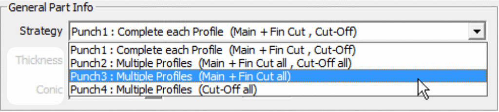
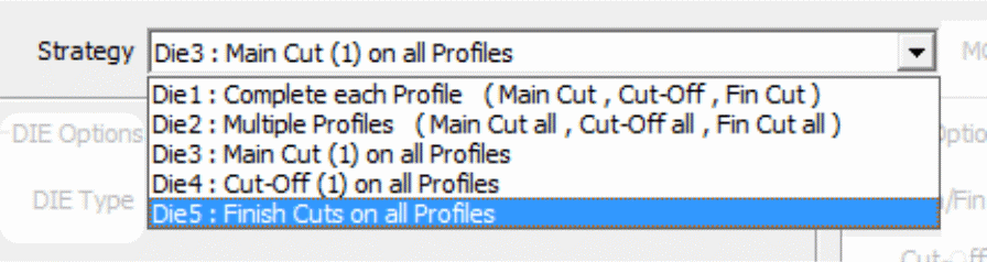
Note:
Once the “Punch3” (Main & Fin) or “DIE3” (Main Cut) for all parts have been defined, the easiest way to create the subsequent final “Cut-Off” or “Finish” worksteps is using the “Spreadsheet” to copy the existing worksteps and then changing the “Strategy” setting to “Cut-Off” or “Finishing”.
MILL / TURN / EDM – Updated “Check Angle” command:
The “Check Angle” command (see “View/Check” menu) can now be used to display the angle between two selected surfaces.
MILL / TURN / EDM – STL Export:
Surfaces can now be exported as STL file.
Telephone: 0116 267 5588